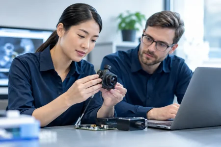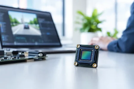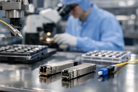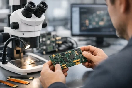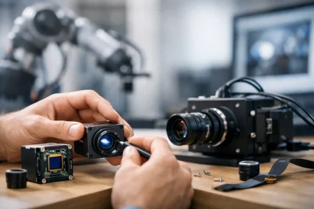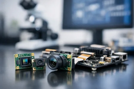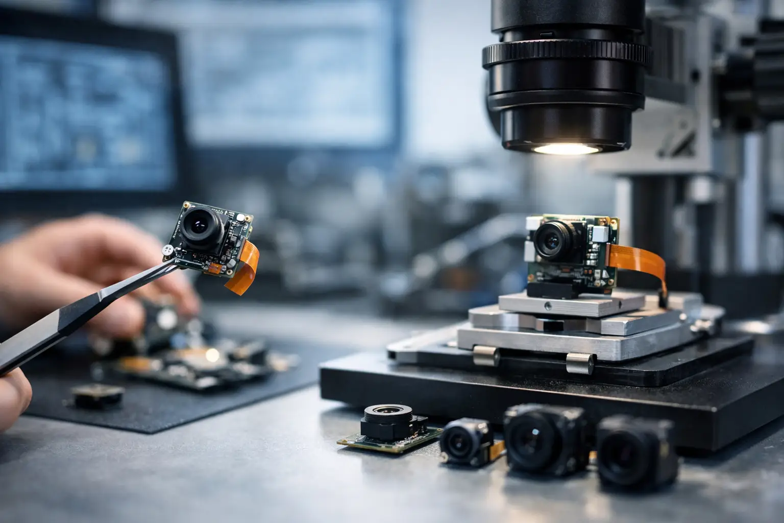
A camera prototype can produce a sharp image on a lab bench and still fail the product program. The failure often appears later: an FPC cannot bend within the enclosure, the MIPI lane configuration does not match the processor, infrared response is wrong for the actual lighting, or the selected component cannot support stable volume supply. Rapid prototyping camera modules should reduce those risks early, not simply put a camera on a board faster.
For OEMs, device makers, and system integrators, the real objective is a prototype that gives engineering teams reliable evidence. It must show whether image quality, mechanical fit, electrical performance, software integration, and manufacturability can move forward together. That requires more than choosing a sensor with the highest resolution.
Why Rapid Prototyping Camera Modules Need Production Thinking
A prototype is a decision-making tool. It should help a product manager confirm a feature set, allow firmware engineers to tune an image pipeline, and give mechanical teams real dimensions for enclosure development. If the module is built without considering the production path, every later change can restart testing and extend the release schedule.
The fastest approach is usually to begin with proven module architecture, then customize the elements that affect the application. A standard MIPI or USB module may provide a stable starting point, while lens field of view, FPC length, connector position, frame rate, optical filter, and housing geometry are adjusted for the device. This approach protects time without forcing a one-size-fits-all camera into a specialized product.
Speed also depends on deciding what must be proven in the first sample. For a warehouse robot, low-light motion performance and latency may matter more than maximum pixel count. For a medical accessory, color consistency, compact dimensions, and controlled illumination may be the primary concerns. An industrial inspection system may need global shutter behavior, fixed focus at a defined working distance, and repeatable image output across a production batch.
Define the Imaging Requirement Before Selecting Parts
A useful camera specification starts with the scene, not the catalog. Ask what the camera needs to see, from what distance, under which illumination, and at what movement speed. Those answers determine the sensor, lens, filter, and interface far more effectively than a resolution target alone.
Start With the Field of View and Working Distance
Field of view and working distance set the optical foundation. A wide-angle lens can capture more of the scene, but it may introduce distortion and reduce the pixel density on a small feature. A narrow field of view can improve inspection detail at distance, but it increases alignment sensitivity. Fixed-focus modules are efficient when the subject range is controlled. Auto-focus can add flexibility, but it introduces power, mechanical, control, and qualification considerations.
Lens selection should also account for aperture, depth of field, distortion, chief ray angle, and temperature behavior. In compact products, a lens that meets the optical target but exceeds the available Z-height is not a valid option. Mechanical constraints must enter the discussion at the same time as image quality.
Match the Sensor to the Actual Scene
Sensor choice is a balance of resolution, pixel size, shutter type, sensitivity, frame rate, power consumption, and cost. A higher-resolution sensor can improve detail, but it increases data bandwidth, memory demand, processing load, and potentially module cost. If the host processor cannot handle the output reliably, the extra pixels create a system problem rather than a product benefit.
Rolling shutter sensors suit many consumer, security, and static-scene applications. Global shutter sensors are often the better choice where motion, vibration, rotating parts, barcode capture, or machine vision measurement can cause image skew. For near-infrared imaging, day/night operation, or controlled LED illumination, the optical filter stack and sensor spectral response should be evaluated together.
Establish the Electrical and Mechanical Envelope
Before the first build, define the host platform, interface, power budget, connector type, mounting points, FPC routing path, allowable module dimensions, and heat sources near the camera. These details prevent a prototype from becoming an isolated component that cannot enter the product enclosure.
FPC camera modules are particularly effective when the sensor board must fit a constrained location while the connector sits elsewhere in the device. The bend radius, stiffener position, cable length, shielding needs, and connector orientation should be specified early. A few millimeters of cable routing can determine whether final assembly is practical.
Build a Prototype That Exposes the Right Risks
The first sample does not need every cosmetic detail. It does need the critical functional characteristics. A well-planned prototype program commonly progresses from an engineering sample, to a mechanically representative version, to a pilot-ready module with controlled components and test requirements.
At the engineering sample stage, teams can verify sensor bring-up, basic image output, lens selection, and host compatibility. The next iteration can address enclosure fit, mounting tolerances, cable routing, illumination interaction, and tuning under real operating conditions. Pilot samples should test whether the design can be manufactured consistently, not just whether one unit works.
This sequence matters because camera issues can be coupled. A change in lens holder height can alter focus. A different IR-cut filter can affect color rendering. A longer FPC can influence signal integrity. A new housing can create internal reflections. Treating each change as independent leads to repeated prototype cycles.
For this reason, prototype documentation should capture the approved sensor and lens, interface timing, module outline, optical stack, target focus distance, operating conditions, and acceptance criteria. Images alone are not enough. The next build needs measurable settings that engineering and manufacturing teams can reproduce.
Choose the Interface for Integration, Not Convenience
MIPI CSI-2 is a common choice for mobile, embedded Linux, AI edge, and processor-based products because it supports high data rates with a compact connection. It requires the host to support the selected lane count, data rate, camera clocking, and software driver configuration. Integration can be efficient when the processor platform already has a validated camera pipeline, but board layout and signal integrity must be handled carefully.
USB and UVC camera modules reduce integration effort for many PC-based, industrial, and plug-and-play applications. They can be a practical path for evaluation equipment, kiosks, machine vision peripherals, and systems where a standard video interface is preferred. USB 3.0 provides more bandwidth for higher-resolution or higher-frame-rate output, while USB 2.0 may be sufficient for lower-bandwidth requirements and cost-sensitive designs.
DVP modules remain relevant for certain legacy processors and lower-complexity embedded systems. The best interface depends on the host, cable length, performance target, and development resources. Choosing an interface simply because it is familiar can create avoidable limitations later.
Validate Image Quality in the Conditions That Matter
Bench testing under office lighting provides only a starting point. The module should be evaluated in the lighting, temperature range, vibration environment, working distance, and motion conditions it will encounter in the finished device.
A practical validation plan should cover at least four areas:
- Image performance, including sharpness, color, noise, dynamic range, distortion, focus, and low-light behavior.
- Electrical behavior, including power consumption, startup consistency, interface stability, electromagnetic considerations, and thermal impact.
- Mechanical reliability, including cable strain, connector retention, mounting repeatability, vibration, and enclosure clearance.
- Manufacturing readiness, including assembly tolerances, component availability, test coverage, cosmetic criteria, and lot-to-lot consistency.
The correct test depth depends on the application. A short-use consumer accessory and a continuously operating industrial camera do not require the same validation profile. However, both benefit from clear pass-fail criteria before design changes become expensive.
Image tuning also deserves attention. Sensor register settings, exposure strategy, white balance, noise reduction, lens shading correction, and color processing influence the final image as much as the hardware. When the host ISP handles processing, the camera module supplier and software team need aligned expectations about raw output, supported formats, and tuning responsibility.
Design the Prototype Path for Scaled Manufacturing
A camera module that reaches pilot production should be designed around supply continuity and process control. This includes confirming the availability of the sensor, lens, connector, FPC, passive components, and any custom mechanical parts. A low-cost prototype part can become costly if it has uncertain lead times or limited allocation.
Manufacturing requirements should be considered before the design is frozen. Lens assembly needs controlled alignment and focus verification. Cleanroom handling can reduce contamination risks on sensor and lens surfaces. Electrical testing should verify camera detection, image output, and key functional parameters. Optical inspection should identify dust, scratches, light leakage, or image defects before modules enter final device assembly.
Tolerance design is equally important. If the product requires a fixed working distance, focus tolerance must reflect the combined variation of the lens, holder, sensor position, and customer enclosure. If the module uses an FPC, define the allowable bend and installation position so production operators do not create hidden stress points. These controls convert a successful prototype into repeatable output.
SincereFirst supports this progression with standard camera module platforms, custom optical and mechanical development, fast sample response, and manufacturing capability for programs that must scale beyond evaluation quantities. For buyers, the key is to engage a supplier early enough that prototype choices can be checked against production realities.
Make Each Prototype Cycle Answer a Clear Question
The most efficient camera development programs do not build samples merely to keep activity moving. Each iteration should answer a defined question: Does the chosen lens resolve the required feature? Does the camera operate correctly on the target processor? Does the module fit after cable routing? Can the assembly process hold focus and image-quality requirements?
When rapid prototyping is approached this way, speed becomes more than shorter sample lead time. It becomes a disciplined route from an imaging requirement to a camera module that engineers can integrate, procurement teams can source, and manufacturing teams can build with confidence.