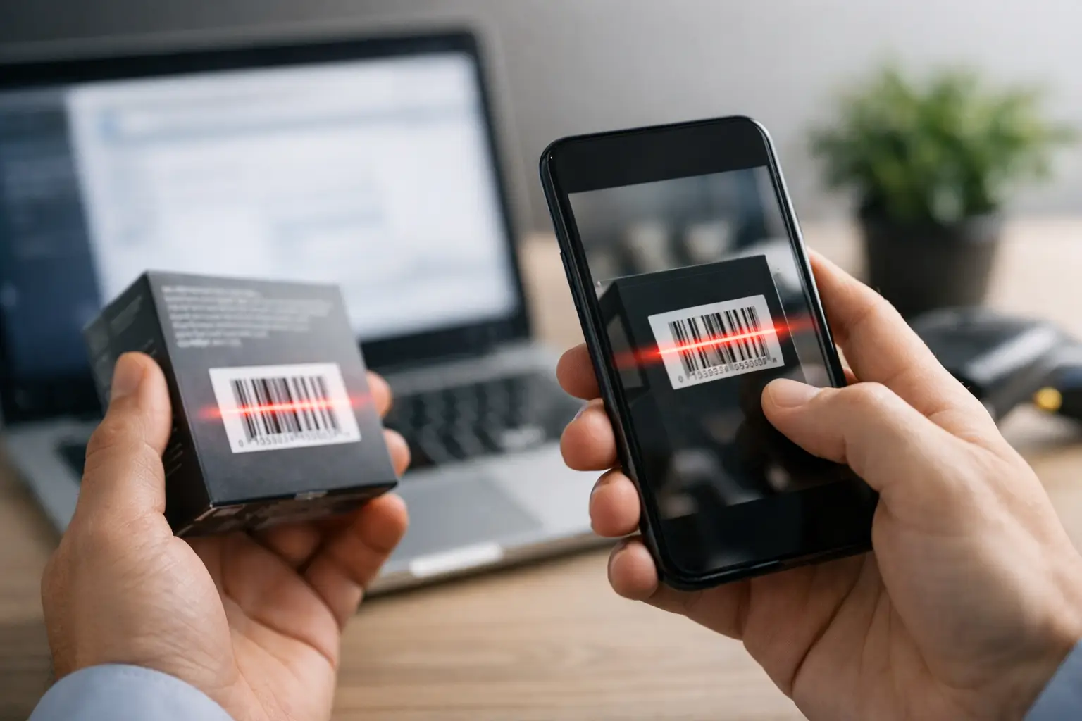
A barcode scanner camera integration example is most useful when it starts with the failure condition, not the camera datasheet. A handheld terminal that reads a clean QR code under office lighting may still fail on a scratched warehouse label, a curved package, or a reflective direct-thermal print. For OEMs and system integrators, the objective is not simply to capture an image. It is to deliver a decodable result quickly, repeatedly, and within the power, space, and cost limits of the finished device.
This practical example outlines how an embedded camera module can become the imaging engine in a fixed-mount or handheld barcode reader. It also shows where camera selection, optics, illumination, firmware, and manufacturing validation must work together.
Barcode Scanner Camera Integration Example for an OEM Device
Consider a battery-powered inventory terminal designed to read 1D barcodes and 2D Data Matrix or QR codes at 100 mm to 450 mm. The device needs a compact scan window, rapid trigger-to-result response, and reliable reading under mixed indoor lighting. It will be produced at scale, so the imaging design must remain manufacturable from prototype through volume production.
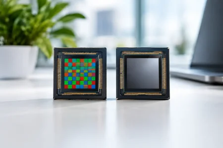
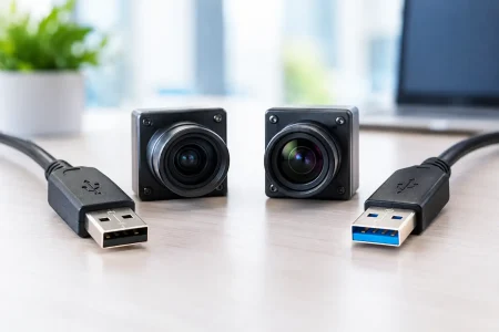
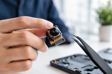
A practical architecture includes a 2-megapixel camera module, a fixed-focus lens, controlled LED illumination, a processor with an ISP and barcode decoding library, and a trigger interface. The module can connect through MIPI CSI-2 in the production device. During early software development, a USB UVC camera module is often useful because it allows the engineering team to validate image quality and decoder performance quickly on a host computer.
The camera captures a triggered frame, the ISP applies controlled image processing, and the decoder searches for barcode patterns. If decoding fails, the system can capture one or two additional frames with adjusted exposure before reporting a failed scan. That sequence sounds simple, but each component affects read rate.
Example imaging targets
For a compact reader with a 70-degree horizontal field of view, a 1920 x 1080 sensor can provide adequate sampling for many common package labels. The final selection still depends on the smallest code, working distance, and required scan area. A wider field of view covers more of a carton at close range, but reduces pixels available for each barcode module.
| Design item | Example target | Engineering reason | |—|—:|—| | Sensor resolution | 1920 x 1080 | Supports 1D and 2D reading while controlling bandwidth | | Interface | MIPI CSI-2 | Low-latency connection for embedded processors | | Focus range | 100 mm to 450 mm | Matches typical handheld inventory use | | Exposure time | 2 ms to 8 ms | Limits blur during normal operator movement | | Illumination | White LED ring or side LEDs | Reduces dependence on ambient light | | Decode response | Under 500 ms | Supports efficient operator workflow |
These values are a starting point, not a universal specification. Reading a 5-mil Data Matrix at longer distance may require more resolution, a narrower field of view, closer focus, or all three. A device expected to scan moving products on a conveyor may need shorter exposure and higher illumination output than a manually operated terminal.
Select the Camera Module Around the Code, Not the Interface
It is tempting to choose a camera by interface first: USB for convenience, MIPI for compact embedded design, or DVP for compatibility with an existing board. The interface matters, but barcode performance begins with optical sampling.
Start by defining the smallest symbol the device must read. For 2D codes, that means the module size, print quality, and quiet zone. For 1D codes, consider narrow bar width, contrast, label damage, and skew. Then calculate how much of the scene must be visible at the nearest working distance. This establishes the needed field of view and approximate pixel density on the code.
A fixed-focus lens is usually the best production choice for a defined reading range. It is smaller, faster, and more repeatable than an autofocus design. Autofocus can help when the application has a very wide range, such as a multipurpose service terminal reading labels from 50 mm to more than 1 meter. The trade-off is added latency, power use, mechanical complexity, and more conditions to validate.
Sensor shutter type also depends on motion. A rolling-shutter sensor is often suitable for a user-triggered scan when the exposure is short. For fast conveyors, vibration-prone equipment, or rapid product motion, a global-shutter sensor can preserve barcode geometry and improve decode consistency. It may cost more and offer different resolution options, so it should be selected for a measured need rather than assumed as a default.
Lighting Is Often the Difference Between a Demo and a Product
Barcode decoding software cannot recover information that glare or shadow has removed. A reliable scanner camera design therefore treats illumination as part of the imaging system.
For matte paper labels, diffuse white LEDs placed around the camera can produce even exposure across the scan zone. For glossy labels, a direct LED ring can create a bright reflection across the code. Moving LEDs off-axis, adding a diffuser, or using a low-angle lighting geometry can reduce this problem. The correct answer depends on package material, label finish, and the angle at which users naturally present the item.
The enclosure matters as much as the LEDs. Internal surfaces near the scan window should be dark and nonreflective so they do not introduce flare. The window material must remain clear after cleaning, abrasion, and expected chemical exposure. If the reader is used in cold storage, outdoor logistics, or medical environments, test the window and illumination assembly under the actual temperature and cleaning cycle.
Ambient-light rejection should also be evaluated. Exposure control that works under fluorescent office light may behave differently near a loading-bay door or under pulsing LED fixtures. A practical firmware strategy is to use a short, controlled LED pulse synchronized with image capture, then tune gain and exposure limits so the barcode remains sharp rather than merely bright.
Build the Firmware Pipeline for Fast Decisions
A barcode reader does not need to stream maximum-quality video continuously. In a triggered design, the lowest-power approach is to keep the camera in standby, wake on trigger, illuminate the target, capture a limited frame sequence, decode locally, and return to standby.
The image signal processor should be configured conservatively. Excessive noise reduction can erase fine bars or modules. Overaggressive sharpening can create false edges that slow decoding. Automatic white balance generally has little value for monochrome barcode contrast, while auto exposure can be useful if it is constrained to a known scan time. Engineers should inspect saved failure images during development rather than relying only on decoder pass or fail statistics.
The decoder receives either a grayscale image or a luminance plane. Cropping to an expected scan region can reduce processor load and response time, particularly on lower-power embedded platforms. However, a tight crop can create field failures when users present labels off-center. The best region of interest is based on observed behavior, not a perfectly centered lab test.
For MIPI camera integration, validate lane configuration, clocking, pixel format, ISP tuning, buffer allocation, and thermal behavior early. A module that produces stable images over USB may still expose timing or driver issues when connected directly to the production processor. Prototype boards should include access for image capture and test points, because visual inspection remains one of the fastest ways to isolate an integration problem.
Validate with Real Labels and Real Operators
A barcode scanner should be qualified with a controlled test matrix that reflects its commercial environment. Clean sample codes alone are not enough. Include labels with low contrast, glossy laminate, wrinkles, print voids, partial damage, curved placement, and varying code sizes.
Measure first-pass decode rate, average response time, worst-case response time, and false-read behavior. Test at the minimum and maximum working distances, across presentation angles, and under low and high ambient light. If the product is handheld, include realistic hand movement. If it is fixed-mount, include target speed and vibration.
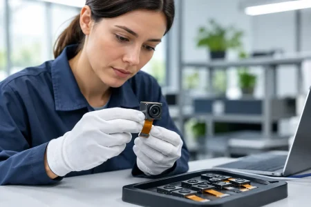
Manufacturing validation deserves equal attention. Lens position, focus tolerance, LED output, scan-window alignment, and sensor calibration can each affect finished-device performance. A production-ready design should define image-based end-of-line checks, not just electrical continuity checks. A reference target and automated decode test can identify modules or assemblies that fall outside the intended optical performance range before shipment.
Plan for Prototype Speed and Production Control
Early evaluation benefits from flexible modules and accessible tuning controls. Production needs controlled bills of materials, stable optical performance, and a clear process for component substitutions. Those requirements should be addressed together, especially when the device will be manufactured across multiple build stages.
For specialized scanner products, SincereFirst can support the transition from a standard camera module evaluation to a customized imaging assembly with selected sensor, lens, FPC layout, interface, and mechanical constraints. The most effective project brief includes code type, minimum symbol size, reading distance, field of view, lighting environment, enclosure window details, processor platform, and expected annual volume.
A barcode reader earns trust one scan at a time. Build the first prototype around measurable image quality, then carry the same optical targets into factory test. That discipline gives the decoder the information it needs and gives the finished device a better chance of performing reliably in the hands of real users.