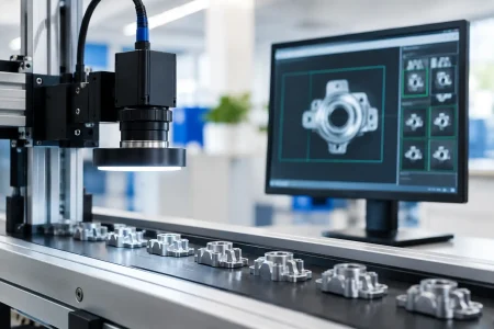
A camera module can have adequate resolution, a well-matched lens, and a capable image signal processor, yet still miss the feature that matters most. In automated inspection, the difference is often illumination. This machine vision lighting design guide is written for OEM engineers and integrators who need to turn a visible defect, code, edge, or surface condition into a stable image measurement at production speed.
Lighting is not an accessory added after camera selection. It is part of the imaging system. The light’s position, angle, wavelength, uniformity, and timing determine the contrast delivered to the sensor. A practical design starts by asking a direct question: what must be visible, and what must disappear?
Why illumination determines inspection reliability
Machine vision algorithms work with grayscale or color values, not with the physical object itself. If a scratch, missing component, embossed character, or contamination mark does not create repeatable contrast at the sensor, even advanced software has little useful information to process.
This is why a trial image taken under room lighting is rarely a valid proof of concept. Ambient light changes with shift conditions, nearby equipment, window exposure, and enclosure position. Reflective parts also change appearance with minor variation in angle. A production system requires controlled illumination that produces a predictable image across normal part, defect part, lot, and operating-condition variation.
The objective is not always the brightest possible image. Excess illumination can saturate highlights, hide texture, create lens flare, or force an unnecessarily short exposure margin. The better target is signal separation: a defect or feature should be clearly different from its background while preserving enough dynamic range for process variation.
Machine vision lighting design guide: define the inspection first
Before selecting an LED ring light, backlight, or controller, document the inspection task in measurable terms. Identify the smallest feature to detect, its expected contrast, the material and finish of the part, the field of view, working distance, part motion, and required cycle time. Also record whether the part can rotate, shift, or vary in height.
A brushed metal housing, glossy black molded plastic, transparent vial, printed flexible circuit, and matte cardboard label may all use the same camera interface, but they demand very different illumination strategies. Surface finish is especially consequential. Diffuse light can reduce glare on a curved reflective part, while low-angle directional light can make shallow scratches stand out. Neither is universally better.
Specify the pass/fail condition as an image condition. For example, instead of stating that the system must inspect a laser mark, define whether it must read characters, verify character presence, detect shallow engraving depth variation, or locate a mark relative to a mechanical datum. Each requirement may lead to a different lighting geometry.
Build samples that represent production variation
Lighting decisions based on one ideal sample are a frequent source of late-stage failures. Evaluate known-good and known-bad parts from multiple lots, including parts with acceptable cosmetic variation. Include changes in color, reflectivity, texture, contamination, position, and temperature when they are relevant to the application.
This approach exposes a key trade-off early. A lighting setup that gives dramatic contrast on a single sample may be too sensitive to routine variation. A slightly less dramatic image with consistent separation across the full sample set is usually the better production design.
Select the lighting geometry by feature behavior
Geometry controls how light interacts with the object and reaches the lens. For many applications, the right geometry has more impact than increasing sensor resolution or light output.
- Backlighting places the object between the light and camera. It creates a high-contrast silhouette and is effective for gauging outer profiles, hole presence, pin position, fill level, and edge defects. It does not reveal surface texture well because the camera primarily sees shape.
- Bright-field front lighting directs light toward the viewed surface. Ring lights and bar lights are common examples. This method can support general presence inspection, label reading, assembly verification, and color evaluation, but shiny parts may produce distracting hotspots.
- Dark-field lighting uses a low illumination angle so smooth surfaces reflect light away from the camera while raised edges, particles, scratches, and texture scatter light toward it. It is often effective for inspecting etched marks, small burrs, surface contamination, and shallow defects.
- Diffuse dome lighting surrounds the part with broad, even illumination. It is a strong option for curved, glossy, metallic, or uneven surfaces where direct lighting produces glare. The trade-off is that diffuse light can reduce the contrast of fine texture or shallow relief.
- Coaxial lighting sends light through optics aligned with the camera axis. It works well on flat, reflective surfaces such as wafers, polished metal, printed codes, and glass, where a uniform frontal reflection is useful. Performance drops on highly curved or strongly textured parts.
Many demanding inspections combine geometries. A component may use backlighting for dimensional verification and dark-field illumination for burr detection. Separate images are often more reliable than forcing one lighting condition to solve two fundamentally different tasks.
Choose wavelength and color with purpose
White LEDs are flexible and convenient, especially when true color is part of the inspection. However, monochrome cameras with narrow-band illumination can produce stronger, more repeatable contrast for a targeted feature.
Red illumination is commonly used for general industrial tasks and can reduce the influence of some ambient light sources. Blue light can enhance contrast for certain surface features and may reduce the apparent impact of red or brown markings. Infrared can help distinguish materials, read through some inks, or reduce the visibility of printed graphics, although sensor sensitivity and lens transmission must be confirmed at the selected wavelength.
The material response matters more than a general rule about LED color. Test the object under candidate wavelengths, then compare histogram separation and defect visibility rather than judging images by appearance alone. If using a color camera, verify white balance, color rendering, and any automatic image processing are locked down for production.
Polarization is another useful tool for glossy surfaces. A polarizer over the light combined with a cross-polarizer on the lens can suppress specular reflections. This can make printing or surface contamination easier to inspect. The cost is reduced light throughput, so the exposure time, gain, aperture, and LED intensity need to be reconsidered together.
Match lighting output to camera, lens, and motion
Illumination design cannot be separated from camera module selection. Sensor pixel size, quantum efficiency, shutter type, frame rate, and noise performance set the available image margin. Lens aperture, working distance, depth of field, and lens coatings affect how much light reaches the sensor and how evenly the field is rendered.
For moving parts, strobe lighting is often preferable to continuous illumination. A short, high-intensity pulse can freeze motion while maintaining a low camera exposure time. The lighting controller, camera trigger, and system timing must be synchronized. Trigger jitter or an unstable strobe pulse can create inconsistent brightness that resembles an inspection problem.
Global shutter sensors are generally preferred where motion measurement or fast conveyor inspection is required because every pixel is exposed at the same moment. Rolling shutter cameras can still be appropriate for stationary scenes or carefully controlled motion, but they should be evaluated for distortion and brightness variation under pulsed lighting.
Avoid relying on automatic exposure and automatic gain in a pass/fail inspection unless their behavior is deliberately controlled. These functions can compensate for a real process change and reduce the visibility of a defect. Fixed, validated settings make image variation easier to diagnose.
Design the mechanical environment around the light
The optical design may work on a bench and fail inside a machine if the mounting, enclosure, and maintenance plan are ignored. The light must be positioned repeatably, protected from vibration, and accessible for cleaning or replacement. A small change in angle can materially alter reflections on polished parts.
Use shielding or an enclosed inspection cell when ambient light could enter the field of view. Select appropriate thermal management for high-output LED assemblies, especially with sustained operation or high-frequency strobes. LED output declines over operating life, so the acceptance threshold should retain margin for expected aging, contamination, and normal optical drift.
Cable routing and electrical noise also deserve attention. High-current strobe drivers, triggers, camera data lines, and power supplies should be integrated as one system. Stable grounding and disciplined cable design reduce the risk of intermittent timing or image artifacts that are difficult to reproduce during commissioning.
Validate with images, not assumptions
A complete lighting validation should measure image performance over the full operating range. Capture images at minimum and maximum part positions, normal speed and maximum speed, expected temperature range, and representative supply conditions. Check for saturation, glare movement, uneven illumination, motion blur, and contrast loss at the field edges.
Set acceptance criteria that connect image data to the actual inspection decision. For a code-reading station, this may include read rate and confidence across damaged labels. For dimensional inspection, it may include edge-location repeatability. For surface inspection, it should include detection performance against verified defect samples while controlling false rejects.
For custom embedded systems, early coordination between the camera module, lens, illumination, mechanics, and firmware shortens iteration cycles. SincereFirst supports this integrated approach by aligning imaging components and customized camera solutions with the actual optical and manufacturing constraints of the device.
A lighting design is ready for production when it makes the correct decision look easy. If the image requires aggressive algorithm tuning to separate a feature from its background, revisit the illumination first. Better photons at the sensor are usually the fastest path to faster inspection, lower false rejects, and a system that holds its performance after the prototype leaves the lab.