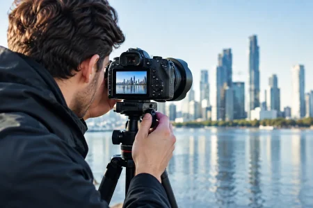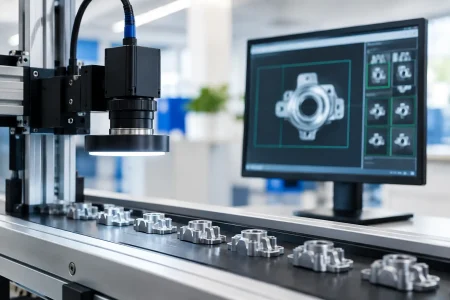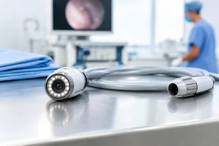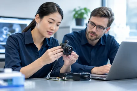
A camera that performs well under office lighting can fail quickly at dusk, inside a warehouse aisle, or within a minimally illuminated medical instrument. Learning how to design low-light cameras starts with a systems-level decision: the sensor, lens, illumination, mechanical envelope, interface bandwidth, and image tuning must be specified together. Raising gain after the image becomes dark is not a low-light strategy. It is usually a fast route to noisy, blurred, or unusable video.
For OEMs and system integrators, the target is not simply a brighter image. The target is repeatable visual information at the required working distance, motion speed, temperature range, and production cost. That distinction drives every engineering trade-off.
How to Design Low-Light Cameras Around the Real Scene
Start with the scene rather than the camera module. Measure or estimate illumination in lux at the object plane, not at the ceiling or near the light source. A security camera viewing a loading dock at 2 lux has different requirements from a robot identifying matte parts at 20 lux, even if both are described as low-light applications.
Define what must remain visible. Is the system detecting motion, reading a label, locating a feature, inspecting a surface defect, or supporting a clinician’s view? Detection can tolerate lower contrast and resolution than identification. Inspection often requires controlled illumination and stable color response, while surveillance may prioritize broad dynamic range and motion performance.
Motion is the constraint that often changes the design. A long exposure gathers more photons, but it also produces blur. If a conveyor moves quickly or a mobile robot vibrates, exposure time may need to stay below a few milliseconds. In that case, a larger sensor, faster lens, supplemental illumination, or lower frame rate may be more effective than exposure extension.
Environmental conditions also matter. Bright entrances, headlights, reflective metal, infrared sources, and flickering LED fixtures create challenges that a basic lux figure cannot describe. Capture representative scene data early, then set measurable acceptance criteria for noise, blur, signal-to-noise ratio, color accuracy, and detection performance.
Select the Sensor for Photon Collection
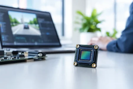
Low-light performance begins with the number of useful photons captured by each pixel. Larger pixels generally collect more light, which can improve sensitivity and reduce the need for aggressive gain. However, pixel size is only one variable. Quantum efficiency, conversion gain, read noise, full-well capacity, backside illumination, and sensor architecture all influence the final image.
A larger optical format can support larger pixels and better low-light behavior, but it increases lens size, module thickness, power consumption, and cost. For compact products, the practical decision is often to use the largest sensor format that the mechanical design and target lens can support without compromising manufacturability.
Resolution deserves equal scrutiny. More megapixels do not automatically create more usable detail in dim scenes. If the same sensor area is divided into smaller pixels, sensitivity per pixel can decline. A 2 MP or 5 MP sensor may outperform a higher-resolution alternative when the application requires reliable recognition under low illumination rather than digital zoom or fine still-image detail.
Evaluate sensor specifications beyond headline sensitivity claims. Useful questions include: What is the read noise at the planned frame rate? Does the sensor provide high conversion gain or dual conversion gain modes? How does it perform at elevated temperature? Is there a low-power mode appropriate for battery-operated products? Does the interface support the selected resolution, bit depth, and frame rate without creating a bandwidth bottleneck?
For many embedded designs, RAW output through MIPI CSI-2 provides the greatest flexibility for image signal processor tuning. USB UVC modules can reduce integration effort for host-based systems, but the available onboard processing and compression behavior should be verified under low-light conditions. Interface selection should follow the total imaging architecture, not convenience alone.
Match the Lens to the Sensor and Working Distance
A sensitive sensor cannot compensate for an underspecified lens. Lens aperture is expressed as an f-number, and a lower f-number allows more light to reach the sensor. Moving from F/2.8 to F/1.4 can significantly improve light transmission, but it also introduces design consequences: reduced depth of field, tighter focus tolerances, larger optics, and potentially higher cost.
The right aperture depends on the task. For fixed-distance barcode reading or a tightly controlled inspection station, a fast lens may be practical. For a camera that must keep objects sharp from near to far distances, stopping down may be necessary, which increases the need for illumination or sensor sensitivity.
Lens transmission is not identical to f-number. Coatings, glass selection, infrared-cut filtering, and mechanical construction affect the actual light reaching the sensor. Evaluate the complete lens-sensor combination rather than comparing lens labels in isolation. Poor corner performance, flare from point lights, chromatic aberration, and focus shift can reduce usable low-light image quality even when the nominal aperture is fast.
For near-infrared imaging, standard visible-light optics may not hold focus when IR illumination is active. An IR-corrected lens, appropriate filter strategy, and sensor response curve should be selected as a matched set. This is especially relevant for access control, nighttime security, agricultural monitoring, and industrial systems operating after hours.
Control Exposure, Gain, and Frame Rate
Exposure, analog gain, digital gain, and frame rate form a connected control loop. Increase exposure first when motion permits. Prefer analog gain over digital gain where possible because analog gain amplifies the sensor signal before digitization, although it also amplifies noise. Digital gain can make the image look brighter but cannot recover information that was never captured.
Frame rate is a commercial and engineering decision. Reducing from 60 fps to 30 fps doubles the maximum exposure time available per frame. Reducing to 15 fps may provide another major sensitivity gain, but only if the end use can tolerate lower temporal resolution. A monitoring camera may be acceptable at 15 fps. A robot guidance or fast inspection system may not be.
Auto-exposure algorithms need application limits. Without guardrails, an algorithm may select an exposure time that creates unacceptable blur or oscillate when headlights and reflections enter the scene. Set minimum and maximum exposure, gain ceilings, frame-rate behavior, and region-of-interest metering based on the actual scene.
Treat Noise Reduction as Image Preservation
Low-light image processing should preserve decision-critical details, not merely create a clean-looking image. Temporal noise reduction can be highly effective on static scenes, but it may smear moving edges. Spatial denoising can soften texture and erase fine defects. Aggressive sharpening can create false edges and unstable detail.
The best tuning sequence starts with clean RAW data. Correct defective pixels, black level, lens shading, and fixed-pattern noise before applying color correction, demosaicing, denoising, and sharpening. Then test the output on real scenes with motion, mixed illumination, and low-contrast targets. A flat laboratory chart is useful, but it cannot represent a reflective machine part, a dark fabric surface, or a person walking through uneven lighting.
High dynamic range is valuable when a dark foreground sits next to bright signage, windows, or headlights. Yet HDR can create motion artifacts when multiple exposures are combined. Use it when scene contrast demands it, not as a default feature checkbox.
Add Illumination When the Application Allows It
Active illumination is frequently the most reliable way to improve low-light performance. White LEDs support natural color imaging and general inspection. Near-infrared LEDs can illuminate a scene without visible glare, making them useful for nighttime monitoring and certain machine vision tasks.
Illumination design must account for wavelength, beam angle, standoff distance, thermal management, eye-safety requirements, and target reflectivity. A ring light can reduce shadows in close-up inspection, while an off-axis light may reveal surface texture or defects. Pulsed illumination can freeze motion while limiting average power, provided the sensor exposure and LED driver are synchronized accurately.
Do not assume more LED power is the answer. Hotspots, reflections, uneven coverage, and thermal drift can reduce image consistency. Controlled lighting geometry often delivers better results than simply increasing brightness.
Build for Repeatable Manufacturing
A low-light design that works on an engineering bench must also survive volume production. Lens alignment, focus position, sensor-to-lens spacing, IR filter placement, adhesive curing, and module shielding can all affect image quality. Tight optical tolerances become more critical as aperture increases and depth of field decreases.
Define production test conditions early. Test modules for sensitivity, white balance, dark-frame noise, hot pixels, focus, color response, and interface stability. If the product will operate across temperature extremes, validate image behavior after thermal cycling. For regulated medical or industrial applications, establish traceability and image-quality acceptance limits that procurement and quality teams can audit.
Working with an experienced module manufacturer can shorten the path from sensor selection to validated samples. SincereFirst supports this process through customized embedded camera modules, optical integration, and scalable manufacturing for machine vision, medical, robotics, and industrial products.
The strongest low-light camera is rarely the one with the highest gain or the largest specification sheet. It is the one designed around the exact photons available, the details the system must retain, and the production controls needed to deliver that performance consistently.