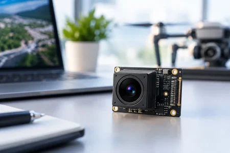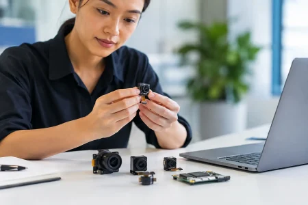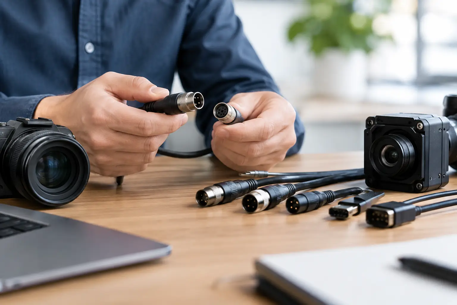
A camera module can meet every optical and sensor requirement on paper, then fail in qualification because the connector choice was treated as an afterthought. Knowing how to select camera connectors means evaluating the complete signal path: camera interface, board layout, cable routing, assembly process, environmental exposure, and the long-term availability needed for production.
For OEMs, system integrators, and embedded product teams, the best connector is not necessarily the smallest or lowest-cost option. It is the one that preserves image data integrity, fits the mechanical envelope, survives the expected service life, and can be sourced consistently at volume.
Start With the Camera Interface, Not the Connector
The interface between the image sensor or camera module and the host processor sets the first boundaries of connector selection. MIPI CSI-2, DVP, USB 2.0, USB 3.0, LVDS, and Ethernet-based camera architectures have very different electrical and mechanical requirements. A connector that works well for a low-speed DVP module may be unsuitable for a high-speed MIPI CSI-2 design.
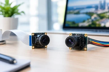
MIPI CSI-2 typically uses differential data lanes plus a clock lane, with control and power lines carried through the same FPC assembly in many compact camera modules. The connector must support the required lane count, pin assignment, pitch, and signal quality. It also needs to match the FPC tail specified for the module. A 15-pin, 22-pin, or 24-pin format may look familiar across products, but pinouts are not automatically interchangeable. Confirm the complete schematic-level pin definition before approving a connector.
DVP camera modules use parallel data signals and separate synchronization lines. They can require more pins than an equivalent MIPI design, especially when power, I2C control, reset, and clock signals are included. USB camera modules simplify the host connection because USB is standardized at the system level, but the internal board-to-module connector and cable assembly still need to meet high-speed signal requirements.
Do not select a connector solely by its number of contacts. Pin count is only useful after the interface, power rails, grounding strategy, and control signals have been fully defined.
How to Select Camera Connectors by Electrical Requirements
Electrical performance is the main reason a connector that appears mechanically correct may create unstable images, dropped frames, or intermittent detection failures. For high-speed camera data, signal integrity must be reviewed as a system rather than as an isolated connector specification.
First, verify the connector’s rated data performance for the intended interface and cable length. Differential pairs used by MIPI CSI-2 or USB 3.0 require controlled impedance through the host PCB, connector, FPC or cable, and camera module. Poor impedance continuity can increase reflection, insertion loss, crosstalk, and electromagnetic interference. These effects become more visible as lane rates rise and cable routing becomes longer.
Second, check current capacity and voltage rating for every power pin. A compact camera may only draw modest average current, yet startup behavior, integrated LEDs, autofocus actuators, heaters, or image-processing components can raise peak demand. Undersized power contacts can create voltage drop, heat, or inconsistent module operation. Ground contacts are equally important because they provide the return path for both power and high-speed signals.
Third, compare the actual pinout against the connector orientation. Top-contact and bottom-contact FPC connectors are not interchangeable. Nor are front-flip, back-flip, horizontal, and vertical orientations. A reversed contact position can require a different FPC tail or a redesigned board, even when pitch and pin count are identical.
Match Pitch and Form Factor to the Product Architecture
Connector pitch determines how much space the interconnect consumes and how demanding it will be to manufacture. Fine-pitch FPC connectors are common in mobile, wearable, medical, and compact robotics designs because they reduce board area. The trade-off is tighter placement tolerance, more sensitive handling, and greater dependence on precise FPC alignment.
For a prototype or industrial device with adequate space, a slightly larger pitch can improve assembly yield and field serviceability. For a disposable medical accessory or a compact endoscope camera, space limitations may make a very fine-pitch solution unavoidable. In that case, the connector, flex design, strain relief, and assembly fixtures need to be engineered as one package.
Also evaluate connector height and cable exit direction early. A low-profile right-angle connector may keep the camera board close to the housing, while a vertical connector may simplify routing in a deeper enclosure. The wrong choice can cause a flex cable to bend too sharply, interfere with a lens holder, or place repeated stress on the connector latch.
Consider Mating Cycles and Mechanical Retention
A connector’s mating-cycle rating should reflect how the device will actually be built, tested, serviced, and used. A camera permanently installed during final assembly has different requirements than a module repeatedly disconnected during calibration, maintenance, or product upgrades.
ZIF FPC connectors are widely used because they save space and provide dependable retention when the correct flex thickness and stiffener are used. They are not ideal for uncontrolled repeated handling or applications where a cable may be pulled sideways. Board-to-board connectors can offer a compact, stable connection between stacked PCBs, but they demand accurate alignment and controlled mechanical tolerances.
For moving assemblies such as robot arms, gimbals, agricultural equipment, or portable diagnostic tools, connector retention is only one part of the answer. The cable must have sufficient bend radius, suitable flex life, and strain relief at both ends. Repeated motion should be absorbed by the cable path, not transferred directly into the connector contacts.
Design for the Operating Environment
Industrial and medical imaging systems often operate in conditions that consumer electronics connectors were never designed to handle. Vibration, shock, dust, moisture, temperature cycling, cleaning chemicals, and electromagnetic noise can all change the selection criteria.
A camera inside a sealed smart meter enclosure may use a compact FPC connector with minimal additional protection. A camera installed in factory automation equipment may require stronger latching, cable retention, and a housing design that prevents vibration from working the connection loose. In medical or endoscopic equipment, biocompatibility, sterilization method, sealing strategy, and the intended reuse cycle can shape the entire interconnect approach.
Connector contact plating matters in harsh or high-cycle applications. Gold-plated contacts generally provide better resistance to oxidation and more stable low-level signal performance than lower-cost alternatives, although plating thickness and overall contact design should be evaluated against the actual duty cycle. Avoid assuming a material choice alone solves environmental risk. Mechanical sealing and enclosure design remain decisive.
Validate the Cable and Connector as a Single Assembly
The connector, FPC, and camera module should be specified together. A connector may accept several nominal FPC thicknesses, but the locking force and contact reliability can vary depending on the stiffener, conductor layout, plating, and tail geometry.
Request dimensional drawings for the camera module and connector, then verify the assembled stack-up in CAD before tooling. Confirm the FPC insertion depth, exposed contact length, stiffener position, bend zones, and clearance around the latch. This review catches expensive problems, such as a cable that cannot be inserted after the lens module is installed or a latch that cannot be reached inside the finished housing.
Prototype validation should include more than a basic image check. Test image stability at maximum resolution and frame rate, especially with long cable runs or elevated electromagnetic noise. Perform insertion and removal testing when service is expected. Add vibration, temperature cycling, flexing, and drop tests that reflect the final product environment. A connector that survives a bench test can still fail after repeated motion or thermal expansion.
Build Supply Continuity Into the Specification
A technically correct connector can still become a program risk if it is difficult to source, has a short product life cycle, or is controlled by a single manufacturer. For commercial production, qualify the connector’s availability, lead times, approved equivalents, and revision control alongside its electrical specifications.
This is particularly relevant when a camera module is customized. A small change to FPC length, tail direction, contact orientation, or pinout can affect tooling, assembly yield, and purchasing flexibility. Early coordination between the camera supplier, connector supplier, host-board team, and contract manufacturer reduces late-stage redesigns.
SincereFirst supports this process by aligning camera module interfaces, FPC configurations, and connector requirements during custom imaging development. For high-volume programs, that alignment helps ensure that a compact design remains manufacturable after it leaves the prototype bench.
Make the Selection Decision With a Qualification Matrix
Before releasing the design, compare candidate connectors against the same defined criteria: interface compatibility, pinout, pitch, current capacity, signal performance, mating cycles, retention, environmental suitability, assembly method, cost, and supply status. This makes trade-offs visible instead of allowing a low unit price or familiar part number to drive the decision.
The right camera connector is a controlled engineering decision, not a catalog shortcut. When the interface, mechanics, test conditions, and production plan agree, the connection becomes one less source of risk between the image sensor and the intelligent device it serves.