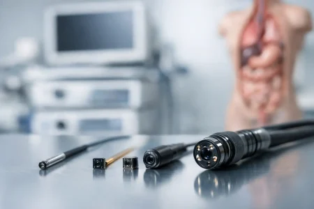
A USB camera module can look simple on paper and still create delays once it reaches the prototype bench. The reason is that how to integrate USB camera module hardware is rarely just a connector decision. It affects optics, power, thermal behavior, housing tolerances, image tuning, cable routing, and long-term production stability.
For product teams building medical devices, robotics, kiosks, security equipment, or industrial systems, the best results come from treating the camera as a subsystem early in development. If integration starts only after the mainboard and enclosure are frozen, you usually end up compensating for noise, focus shift, poor lighting, or mechanical constraints that were avoidable.
How to integrate USB camera module into a product
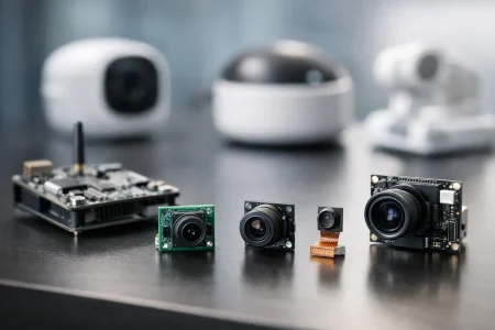
The first decision is not resolution. It is defining the job of the camera. A barcode reader, telemedicine terminal, agricultural monitor, and inspection device may all use USB, but their imaging priorities are different. One may need fast autofocus, another low distortion, another strong low-light performance, and another stable fixed focus with high consistency across units.
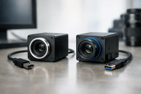
That use case should drive sensor selection, lens choice, USB interface version, board shape, and image processing requirements. USB 2.0 can be enough for many 720p and 1080p applications where bandwidth is moderate and cost matters. USB 3.0 becomes the practical choice when frame rate, resolution, or low-latency video transfer is more demanding. The trade-off is usually cable quality, power budget, and system cost.
UVC support also matters early. If the end product needs plug-and-play behavior across Windows, Linux, or Android platforms, a UVC camera module can reduce driver work and shorten development time. But UVC does not remove all integration work. Exposure behavior, white balance tuning, field of view, startup timing, and host compatibility still need validation in the target device.
Start with the system, not the module alone
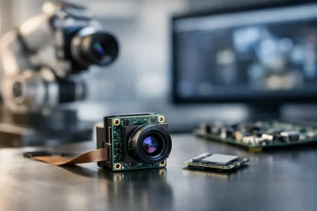
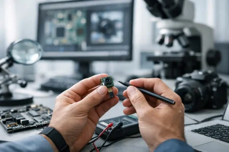
Engineers sometimes evaluate a camera module on a desktop test board and assume performance will carry into the final product. That is where problems begin. A camera that looks excellent in an open lab setup can perform poorly inside a compact enclosure with nearby heat sources, reflective surfaces, and limited illumination.
Mechanical stack-up is one of the biggest hidden variables. Lens height, board thickness, connector orientation, adhesive position, and bracket tolerances all affect final alignment. Even small shifts can change the chief ray angle response, introduce shading, or move the focal plane enough to reduce image sharpness at the working distance that matters most.
This is why serious integration planning includes the enclosure, lens window, IR filter strategy, and cable path at the same time. If the product uses a cover glass, that glass must be considered part of the optical system. Thickness, coating, contamination risk, and spacing from the lens all affect image quality. In some applications, a low-cost window saves mechanical complexity but creates flare or ghosting that software cannot fix later.
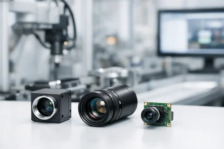
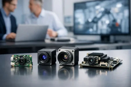
Sensor and lens pairing
The sensor and lens have to be matched for actual scene conditions, not just catalog specs. A higher megapixel sensor is wasted if the lens cannot resolve enough detail or if the product lighting is weak. Likewise, a very wide-angle lens may capture more context but can introduce distortion that is unacceptable for measurement or recognition tasks.
Depth of field matters just as much. Fixed-focus modules are often preferred in industrial and embedded products because they are stable, cost-effective, and easier to qualify over volume production. Autofocus may improve usability in consumer-facing devices, but it adds complexity in motion control, startup behavior, and reliability testing.
Board shape and connector planning
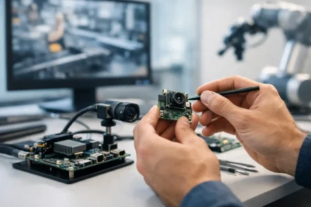
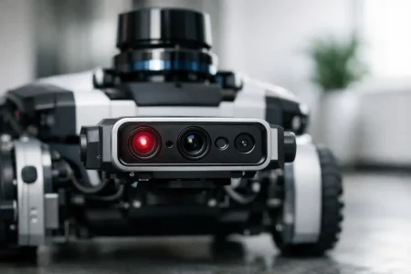
USB camera module integration often fails on packaging, not on imaging. The module board outline has to fit the enclosure, allow assembly access, and maintain secure cable retention. A standard rectangular board may be easy to source but difficult to place in a narrow handheld device or articulated robotic assembly.
At this stage, custom board dimensions, connector locations, microphone options, LED support, and mounting hole positions can save major redesign time later. For OEM and ODM projects, this is often where custom development creates the most value because the camera is being adapted to the product instead of forcing the product to adapt around the camera.
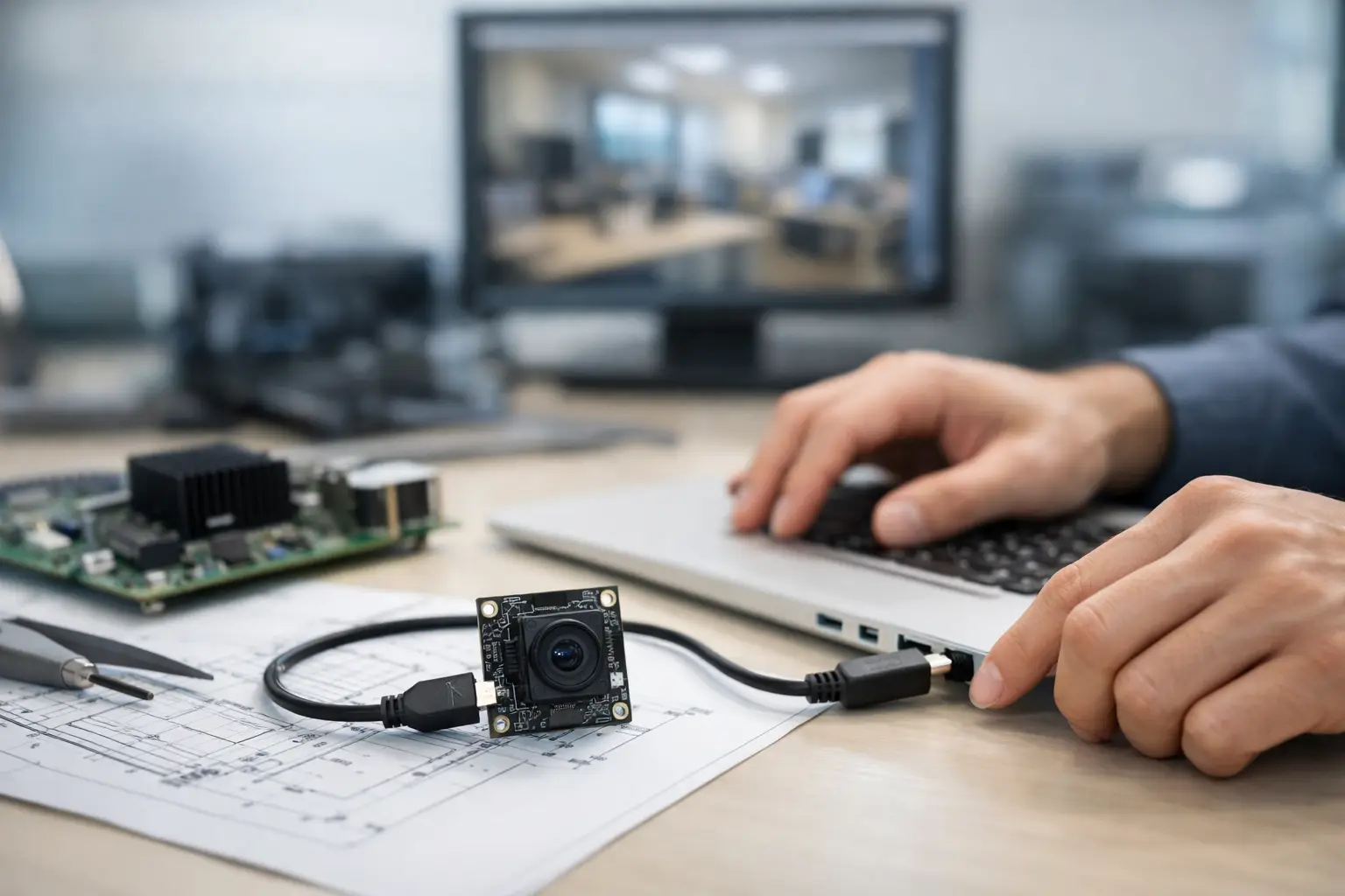
Electrical integration and power stability
USB makes data transfer familiar, but signal integrity still deserves attention. Cable length, shielding, connector quality, grounding, and nearby EMI sources can all degrade camera stability. In industrial environments with motors, switching power supplies, or long cable runs, these issues become more visible.
Power delivery is another common weakness. If the host platform cannot provide stable voltage and current during camera startup or high-load streaming, symptoms may include random disconnects, frame drops, color instability, or failed enumeration. These can look like firmware defects when the root cause is power noise or insufficient margin.
For compact products, thermal rise also needs to be measured under continuous operation. Sensors, ISP components, and nearby processors can raise module temperature enough to affect image noise and long-term reliability. Sometimes the fix is a different placement. Sometimes it requires heat spreading, lower-power components, or adjusted frame rate targets.
Firmware, UVC behavior, and image tuning
A camera module is not production-ready just because the host OS recognizes it. Real integration includes tuning the image for the application. Exposure targets, gain limits, white balance logic, gamma, sharpness, saturation, and backlight handling should be calibrated to the end-use scene.
This is especially important in medical, industrial, and machine vision-adjacent products where repeatability matters more than visual punch. An image that looks bright and vivid to the human eye may be a poor input for downstream analysis. On the other hand, a technically flat image may be exactly right for measurement, OCR, or defect detection.
If the module is UVC-based, define which controls need to remain exposed to the host and which should be locked down for consistency. Too much host-side freedom can create support issues in the field. Too little control can limit system optimization. The right balance depends on whether the product is operated by end users, installers, or a controlled software stack.
Validate in the real environment
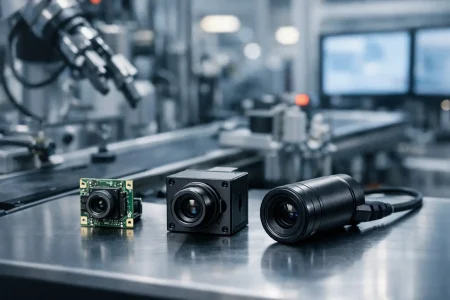
Bench validation is only the first gate. Production-grade validation should reflect the real operating environment, including target light levels, subject distance, motion, vibration, and cable stress. For medical carts, warehouse scanners, outdoor kiosks, and industrial equipment, these conditions are very different.
Low light should be tested with the actual enclosure and window installed. Focus should be checked at the real working distance, not just at a chart distance chosen for convenience. If the product includes LEDs, test the camera with those LEDs active and verify there is no flicker interaction, hotspotting, or color shift.
Environmental and assembly variation matter too. Module performance should be checked across multiple samples, not a single golden unit. In scaled manufacturing, the right question is not whether one sample works. It is whether the design holds performance across batches, operators, and end-product tolerances.
How to integrate USB camera module for production scale
Prototype success is different from manufacturing success. A module that performs well in ten engineering units may still create yield loss if alignment is hard to control, cable insertion is fragile, or focus adjustment depends on manual skill.
That is why manufacturability should be reviewed before the design is locked. Ask whether the camera can be installed repeatably, whether the connector can survive service cycles, whether the lens position is fixed and stable, and whether final inspection can verify image quality efficiently. If not, cost will surface later in rework, scrap, or field returns.
For many B2B device makers, working with a manufacturer that supports both standard USB modules and custom adaptation shortens this path. Teams can start with a proven architecture, then adjust sensor, lens, board size, cable type, and tuning to fit the final device. That approach is usually faster than forcing a fully off-the-shelf module into a product it was not designed for.
SincereFirst typically sees better project outcomes when customers engage on integration constraints early, especially for compact devices and regulated or high-duty applications. Fast samples help, but engineering alignment on optics, interface, housing, and production targets is what keeps schedules under control.
The practical rule is simple: integrate the camera the same way you would integrate any critical subsystem. Define the image task first, validate the module inside the real mechanical and electrical environment, and make sure the design can be built at volume without relying on luck. That is what turns a working demo into a dependable product.