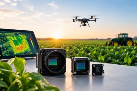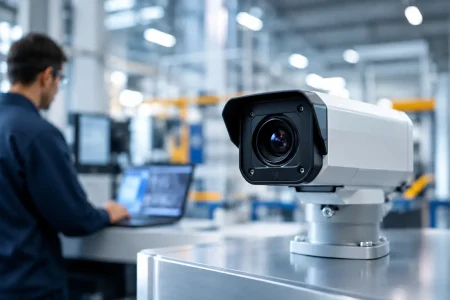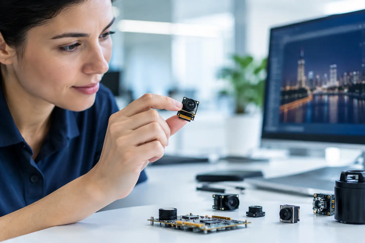
A camera that looks acceptable under a lab bench light can fail quickly in a warehouse aisle, a patient-monitoring room, or a roadside cabinet after sunset. This low-light camera module design guide addresses the engineering decisions that determine whether an embedded imaging product delivers usable detail when photons are limited – not merely a brighter-looking image.
For OEMs and system integrators, low-light performance is a system-level result. The image sensor, lens, IR-cut filter, illumination, ISP, interface bandwidth, mechanical stack-up, and production calibration all affect the final image. Improving one component without checking the others can add noise, blur, heat, cost, or integration risk.
Start With the Image Requirement, Not the Sensor Resolution
The first design question is not “Which sensor has the highest megapixel count?” It is “What must the system recognize at its lowest operating light level?” A security camera may need to identify a person at 10 meters. An autonomous mobile robot may need to detect pallet edges without stopping. A medical or industrial inspection device may need color accuracy, controlled illumination, and very low distortion in a confined space.
Define the operating condition in measurable terms: minimum scene illuminance in lux, target distance, field of view, motion speed, acceptable frame rate, required color performance, and whether active illumination is permitted. Also establish the detail threshold. Detection, recognition, barcode decoding, dimensional measurement, and facial identification require very different levels of image detail.
This requirement determines the practical trade-off between resolution and sensitivity. For a similar sensor format, larger pixels collect more light than smaller pixels. A lower-resolution sensor with larger pixel pitch can therefore outperform a high-resolution alternative in a dark scene, especially when the application requires fast exposure and controlled noise rather than fine daytime detail.
Low-Light Camera Module Design Guide: Choose the Sensor Carefully
Sensor selection should begin with optical format, pixel size, sensitivity, and shutter behavior. A larger optical format generally supports a larger lens aperture and improved photon collection, but it also increases module dimensions, lens cost, and mechanical integration constraints.
CMOS sensors are the standard choice for most embedded modules because they support compact packaging, low power consumption, high frame rates, and broad interface compatibility. Review the sensor’s quantum efficiency, read noise, full-well capacity, dynamic range, near-infrared response, and supported output modes. Datasheet sensitivity figures are useful, but they do not replace validation with the intended lens and ISP.
Pixel binning can improve low-light sensitivity by combining data from adjacent pixels. The cost is reduced effective resolution. This may be a sound trade for security, logistics, and navigation applications where stable motion capture matters more than maximum pixel count. HDR modes also need careful review. They can preserve highlight detail around headlights or bright windows, but some HDR approaches may introduce motion artifacts or reduce performance in very dim scenes.
Global shutter is preferred when motion blur or rolling-shutter distortion would compromise inspection or machine-vision results. However, rolling-shutter sensors can offer stronger sensitivity, resolution, or cost options in certain module sizes. The right choice depends on scene movement, illumination behavior, and exposure time.
Exposure Time, Gain, and Frame Rate Work Together
Longer exposure collects more photons, but it also increases motion blur. Analog and digital gain can lift image brightness, but gain amplifies noise as well as signal. Reducing frame rate permits longer exposure, which can be effective for a fixed surveillance scene but unacceptable for robotics, driver monitoring, or high-speed production equipment.
Set the minimum usable frame rate before tuning exposure. A 1/10-second exposure might improve a static scene, yet it will not produce reliable visual data from a moving conveyor or a mobile platform. This is why a low-light requirement should always include scene motion.
Lens Design Often Decides the Result
A highly sensitive sensor cannot compensate for a lens that transmits too little light. Lens aperture is expressed as an f-number, and lower f-numbers pass more light. Moving from F2.8 to F1.4 can substantially increase light transmission, but the lens may become larger, more expensive, and more difficult to keep sharp across the full field of view.
Wide apertures also reduce depth of field. This can create focus variation when the subject distance changes or when production tolerances shift the lens-to-sensor spacing. For industrial devices, fixed-focus designs must account for the full object-distance range, temperature expansion, vibration, and expected assembly variation.
Evaluate lens transmission, not only the nominal f-number. Coating quality, glass or plastic material, distortion, flare resistance, chief-ray angle compatibility, and infrared behavior all influence the image. Stray light can reduce contrast enough to hide low-contrast objects even when exposure levels appear sufficient.
The image circle must match the sensor format, and the module’s active alignment process must support the required center sharpness and corner sharpness. For compact camera modules, a small tilt or spacing error can be visible at wide apertures. A supplier should be able to define measurable image-quality targets and verify them during production.
Decide Early: Visible Light, NIR, or Both
If the product operates in darkness, active illumination may be more predictable than attempting to extract color information from an extremely dark visible-light scene. Near-infrared LEDs at 850 nm commonly provide stronger sensor response and a faint red glow. LEDs at 940 nm are less visible to people but typically require more optical power or a more sensitive sensor to achieve the same scene brightness.
Day-night cameras commonly use an IR-cut filter for accurate daytime color, then remove or switch the filter for night operation. Without this step, infrared energy can contaminate color rendering during daylight. The filter mechanism adds cost, size, power demand, and moving-part considerations. For applications dedicated to NIR imaging, a fixed no-IR-cut optical path can simplify the module.
Illumination must be designed with the lens field of view. An LED beam that is narrower than the camera view produces a bright center and dark edges. A beam that is too wide wastes power and may create reflections from nearby housing surfaces. In medical, endoscope, and close-range inspection designs, managing specular reflection is often as critical as increasing LED output.
Treat ISP Tuning as Part of Module Development
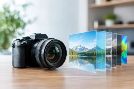
A raw sensor image is not a finished camera output. The image signal processor controls demosaicing, noise reduction, sharpening, white balance, exposure control, tone mapping, defective-pixel correction, and color processing. Poor ISP tuning can make a capable sensor look soft, smeared, unstable, or unnaturally bright.
Noise reduction needs a deliberate balance. Aggressive temporal denoising may produce cleaner-looking footage, but it can erase fine texture, blur moving subjects, or leave trails behind motion. Excessive sharpening can generate false edges that disrupt machine-vision algorithms. For AI-enabled products, tune and validate the camera output using the actual detection or classification model, not visual preference alone.
Low-light testing should include mixed-color light sources, backlit scenes, reflective materials, flickering LED fixtures, and sudden transitions between bright and dark areas. Automatic exposure and white balance must settle quickly without pumping or visible color shifts. If the module uses MIPI CSI-2, USB, or another digital interface, ensure the selected pixel format and frame rate fit the available bandwidth after all required processing.
Design the Electrical and Mechanical Path for Stability
Low-light operation can increase sensor gain, processing load, and LED power. These conditions make thermal design more consequential. Sensor temperature raises dark current and can increase noise during long exposures. LED heating can change output and wavelength, while heat from a processor can affect both the sensor and nearby lens mechanics.
Use a thermal path appropriate for continuous duty, and verify performance after thermal soak rather than only at room temperature. Power-supply noise, grounding, FPC routing, connector selection, and electromagnetic interference control also matter. Noise that is invisible in a bright scene may become apparent as banding, fixed-pattern noise, or frame instability in low light.
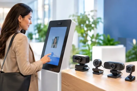
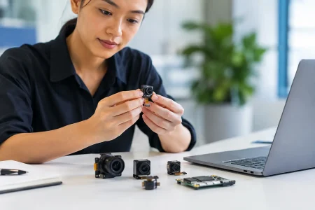
For compact products, the camera module, cable length, host board, and enclosure should be evaluated together. MIPI cameras are efficient for short, high-speed internal connections but require disciplined signal-integrity design. USB UVC modules can simplify host integration and support broader plug-and-play compatibility, though power and cable constraints must still be checked for the intended installation.
Validate for Production, Not Just a Prototype
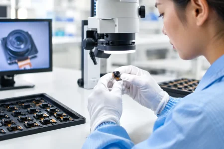
A successful prototype proves feasibility. A manufacturable module proves that the same performance can be repeated across lots. Define incoming inspection criteria for sensors and lenses, active-alignment standards, cosmetic requirements, focus acceptance limits, dead-pixel policy, and end-of-line image tests.
For low-light products, include calibrated dark-scene tests in the production plan. Verify illumination uniformity where LEDs are integrated. Check color and focus under the actual filter configuration. If the product requires compliance testing or use in medical equipment, traceability and change control should be established before volume release.
SincereFirst supports this process with embedded camera module customization, optical selection, interface matching, image tuning, sample development, and scalable cleanroom manufacturing. The practical value is reducing handoffs between component sourcing, optical engineering, module assembly, and production validation.
The strongest low-light camera is the one designed around the scene it must interpret. Give the sensor enough light, preserve that light through the optical path, tune the signal without erasing useful detail, and validate every choice under the conditions your customer will actually face.