A rejected connector housing can cost far more than the part itself when it reaches final assembly: line stoppages, rework, supplier disputes, and potentially a field failure. This automated inspection example shows how a vision system can inspect a small, high-volume component at line speed, while also explaining the engineering choices that determine whether the system delivers dependable results or simply generates more false rejects.
The practical case is an injection-molded electrical connector housing used in an industrial device. Before assembly, the manufacturer needs to verify cavity presence, terminal-position integrity, color, orientation, flash, short shots, and readable lot marking. Manual checks are slow and inconsistent, particularly when defects are subtle and the line runs continuously.
Automated Inspection Example: Connector Housing Verification
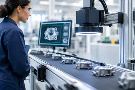
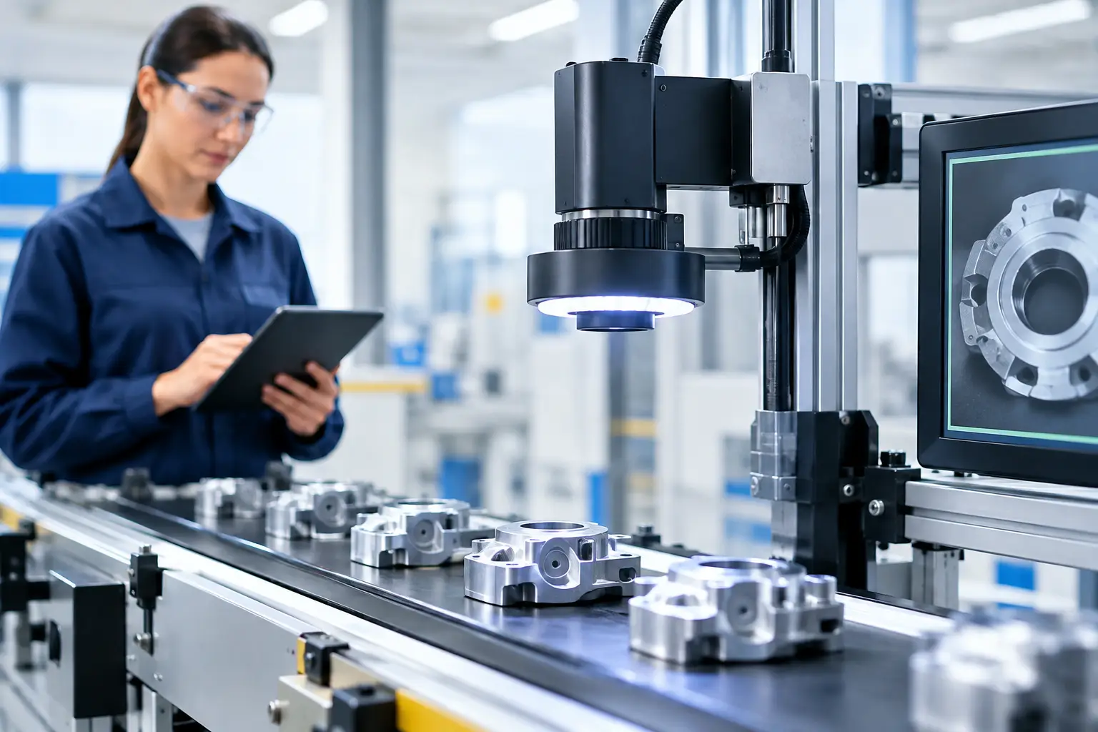
A conveyor presents each connector housing in a repeatable fixture. A photoelectric trigger detects the fixture, starts a strobe pulse, and captures images from two cameras. The first camera views the top face to inspect cavity geometry, molded features, and the lot code. The second views the underside to confirm that latch features and terminal channels are fully formed.
The inspection application compares each image against trained or rule-based acceptance criteria. It measures cavity edges, checks whether required features are present, reads the code, and classifies surface defects. Within the available cycle time, the system sends a pass or fail signal to the PLC. Failed parts are diverted into a locked reject bin, while every result is stored with a timestamp, station ID, recipe version, and image reference.
That basic sequence is familiar. The engineering value comes from making it repeatable across shifts, material lots, ambient conditions, and production ramps.
What the system must detect
The inspection specification should define defects in measurable terms rather than relying on phrases such as “good appearance.” For this connector, a short shot might mean a missing molded edge greater than 0.15 mm. A terminal cavity may need to be open across a specified width. A lot code must meet an agreed character-confidence threshold and match the current production order.
A useful specification also separates critical defects from cosmetic variation. A tiny flow mark may be acceptable; a partial latch that prevents mating is not. Without this distinction, the system will either pass functional risks or reject too many usable parts.
Start With the Inspection Decision, Not the Camera
Camera selection matters, but it is not the first decision. Begin with four production questions: what must be found, how small it is, where it appears on the part, and how much time is available to make the decision.
If the smallest required defect is 0.15 mm, the imaging system needs enough pixels across that feature to distinguish a true defect from image noise or normal dimensional variation. A common target is several pixels across the smallest relevant feature, with margin for focus tolerance and motion. The actual requirement depends on contrast, lens distortion, part positioning, and the inspection algorithm.
Field of view follows from the part size and allowable fixture variation. For example, a 5-megapixel camera viewing a 60 mm-wide area can provide substantially better sampling than a lower-resolution camera viewing the same area. But more pixels also increase data transfer, processing load, storage requirements, and potentially cycle time. Higher resolution is not automatically higher reliability.
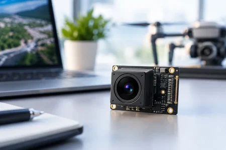
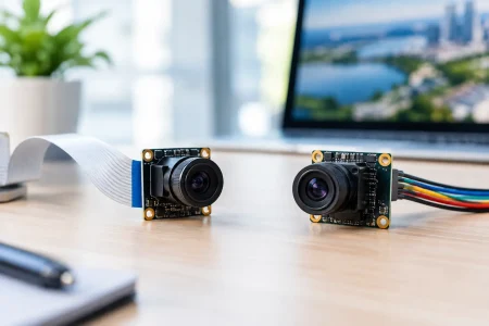
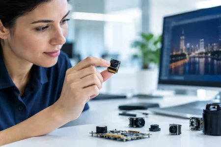
For fixed, high-speed production stations, a global-shutter sensor is often the practical choice because it captures moving parts without the geometric skew associated with rolling shutter exposure. A USB3 camera module can be appropriate for a PC-based inspection cell where bandwidth and rapid integration are priorities. A MIPI camera module may be a better fit for a compact embedded inspection device with constrained size, power, and latency requirements.
Lighting Determines Whether Defects Are Visible
Many vision projects fail because the camera is asked to solve a lighting problem. The same molded connector can look completely different under overhead factory lights, a broad diffuse source, and a low-angle directional light.
For cavity presence and surface uniformity, diffuse dome or panel lighting can suppress glare from glossy plastic and provide even contrast. For flash along an edge, low-angle dark-field lighting can make a raised defect appear bright against a dark background. Backlighting is often effective when the key question is profile, gap, or full feature formation.
In this example, the station may use two controlled lighting modes for one camera position: diffuse illumination for code reading and feature presence, then low-angle strobed light for flash detection. The camera captures separate images after each light pulse. This adds complexity, but it can reduce the temptation to force unrelated defect types into one compromised image.
Shield the inspection zone from changing ambient light, and synchronize strobe duration with exposure. Short, high-intensity pulses help freeze conveyor motion. The objective is not a visually attractive image. It is stable contrast between acceptable and unacceptable conditions.
Build the Mechanical Station for Vision Stability
An algorithm cannot compensate indefinitely for a part that rotates, bounces, or arrives at an unknown height. A low-cost nest, guide rail, or datum feature can improve inspection performance more than a more expensive sensor.
The fixture in this automated inspection example establishes a consistent X, Y, Z location and limits rotation. It should be designed around the part’s functional datums where possible, not a cosmetic surface that may vary. If multiple SKUs share the line, use a recipe-controlled fixture strategy or confirm that the system can locate each part before measurement.
Focus depth needs the same discipline. A wide-aperture lens may provide more light but less depth of field. Stopping down increases depth of field but requires stronger illumination or longer exposure. Telecentric optics can be justified when precise dimensional measurements are required and part height changes would otherwise alter magnification. They are more expensive and larger than conventional lenses, so they should solve a defined measurement risk rather than become a default specification.
Choose Inspection Logic That Matches the Defect
Rule-based vision tools work well when the part, position, and defect signature are controlled. Edge measurement, blob analysis, pattern matching, barcode reading, and optical character verification are transparent methods that are often easy to validate. They can be the right answer for cavity presence, clip geometry, or a clearly printed code.
AI-based classification becomes useful when surface appearance is variable and hard to describe with fixed rules. Examples include irregular scratches, contamination, inconsistent texture, or complex molded appearance. However, AI requires representative labeled images, ongoing review of error cases, and controls for recipe changes. It should not be treated as a substitute for good lighting and fixturing.
A hybrid approach is frequently strongest. Use deterministic measurement for critical dimensions and feature presence, then use a trained classifier to assess irregular surface defects. This keeps safety- or function-critical decisions explainable while allowing the system to handle appearance variation that does not fit simple thresholds.
Validate for False Accepts and False Rejects
The most damaging inspection error is a false accept: a defective component passes and moves downstream. The most disruptive operational error is a false reject: a good component is removed, reducing yield and creating unnecessary review work. The acceptable balance depends on the component’s failure risk, downstream cost, and available containment process.
Validation should use real production parts, including known defects, acceptable edge cases, multiple material lots, and samples from different tooling cavities. Test at actual line speed and under expected operating conditions. A lab demonstration with hand-positioned parts rarely proves production performance.
Track pass rate, reject rate, false accept rate, false reject rate, inspection time, and image-quality alarms. Save images for failed parts and selected passed parts, especially during launch. Image records help engineering teams distinguish a genuine process shift from a vision-system issue.
For regulated medical, automotive, or safety-sensitive applications, traceability requirements may extend to user access, recipe approval, audit trails, and retention periods. Define those requirements before selecting the vision software architecture and storage capacity.
Scale From a Pilot Cell to Production
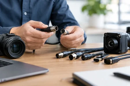
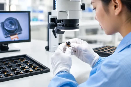
A successful pilot should prove more than defect detection. It should prove that the camera, lens, lighting, enclosure, I/O, cables, and computing hardware can be sourced, assembled, calibrated, and serviced consistently. For OEM equipment builders, module availability and controlled change management can be as important as image quality.
SincereFirst supports this path with standard and custom camera modules for embedded and industrial imaging applications, including USB, MIPI, DVP, and specialized optical configurations. Early evaluation should confirm sensor format, shutter type, interface, board dimensions, focus method, connector orientation, and the environmental conditions the finished equipment must withstand.
When volumes increase, establish a golden sample process and a repeatable camera setup procedure. Lock exposure, gain, white balance, and lighting recipes once validated. If automatic adjustment is necessary, tightly limit its range and log changes. An inspection station that silently changes its own image baseline is difficult to qualify and difficult to troubleshoot.
The best next step is to select one high-cost, well-defined defect family and build the inspection station around the actual production decision. When the optical design, mechanical presentation, and acceptance criteria are engineered together, automated inspection becomes a measurable manufacturing control rather than another screen beside the line.