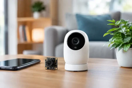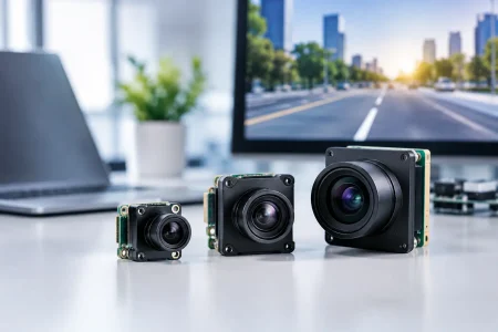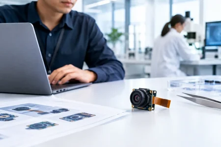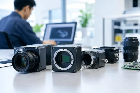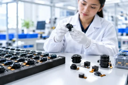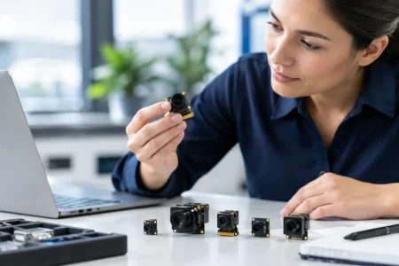

A camera module can deliver excellent sensor performance and still fail at the product level because the interconnect was treated as a minor detail. To integrate camera module connectors successfully, engineering teams must match electrical signaling, mechanical retention, cable routing, assembly processes, and long-term service conditions from the first prototype. The connector is not simply a purchase-line item. It is the physical and electrical boundary that determines whether the camera performs consistently inside the finished device.
How to Integrate Camera Module Connectors Correctly
The correct connector choice starts with the camera interface, not the enclosure drawing. MIPI CSI-2, USB 2.0, USB 3.0, DVP, and custom FPC camera module designs have different signal requirements, pin counts, grounding strategies, and cable-length limits. A connector that fits a flex cable may still be unsuitable for the data rate, electromagnetic environment, or repeated mating cycle required by the application.
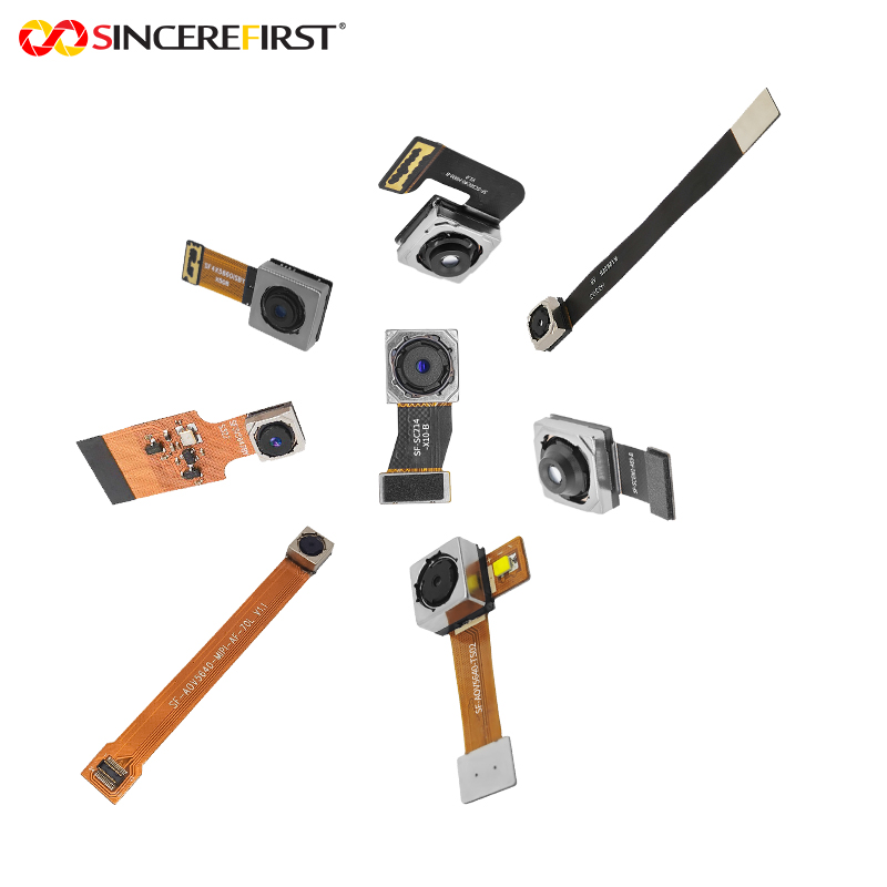
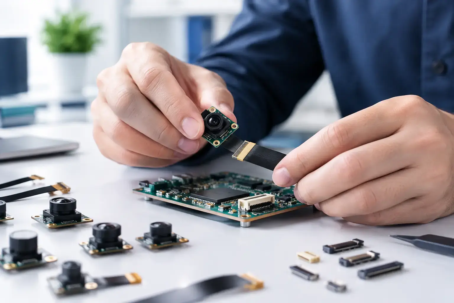
For compact embedded products, FPC and FFC connectors are common because they support low-profile routing between the camera module and the host board. Their pitch, contact orientation, insertion direction, locking method, and tail length must match the module design exactly. A top-contact connector cannot be substituted for a bottom-contact version simply because the pin count is the same. The camera may not power on, or worse, incorrect contact alignment can introduce a risk of damage during bring-up.
Board-to-board connectors are often a better fit when the camera module is mounted directly above or beside the main PCB. They reduce cable handling and can improve assembly repeatability, but they place tighter demands on stack-up tolerance, board flatness, and housing alignment. For serviceable systems, such as industrial inspection equipment or medical device assemblies, a cable-based connection may be preferable even when it consumes more space.
Start with the interface and pinout
Before selecting a connector family, confirm the full electrical definition of the camera module. This includes supply voltages, ground pins, I2C control lines, reset and power-down signals, clock requirements, data lanes, shielding provisions, and any LED or autofocus control connections. Requesting only a connector part number is not enough. The camera module pinout and host-board schematic must be reviewed as one system.
MIPI CSI-2 modules require particular discipline. High-speed differential pairs must preserve polarity and lane assignment from the image sensor through the FPC, connector, and host-board traces. Pair impedance, length matching, via use, return paths, and discontinuities all affect signal integrity. In a short prototype cable, a marginal layout may appear functional. At volume production, temperature variation, cable-source variation, and assembly tolerances can expose intermittent frame loss or camera detection failures.
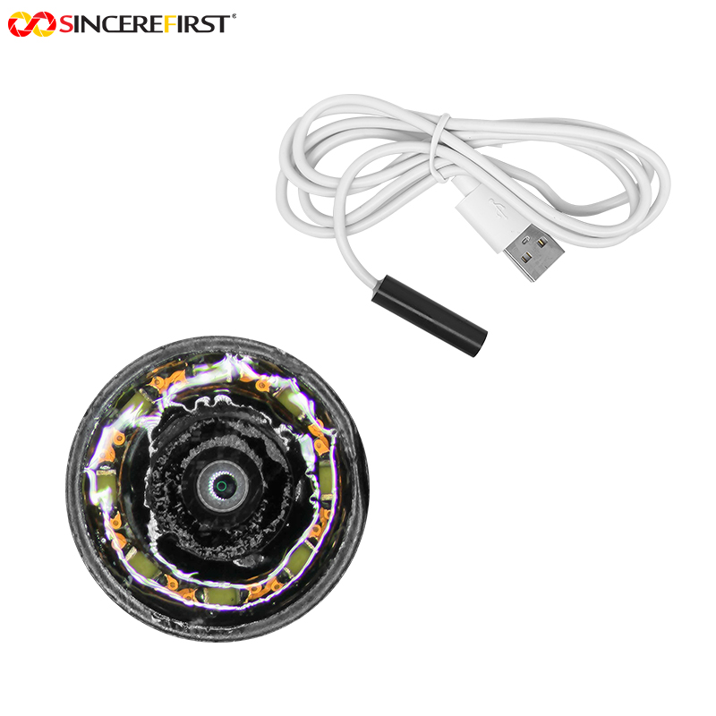
USB camera modules simplify software integration in many cases because UVC support is widely available, but the connector design still matters. USB 3.0 modules need careful routing for SuperSpeed pairs and a controlled ground path. If the product uses a long cable or operates near motors, radios, switching supplies, or LED drivers, shielding and cable construction deserve as much attention as the connector itself.
DVP camera modules use parallel data and timing signals, which can be practical for legacy processors and lower-speed designs. However, a larger pin count can make connector selection more difficult in compact products. Clock skew, crosstalk, and uneven trace lengths can reduce timing margin. The right answer depends on the processor, resolution, frame rate, board area, and available software support.
Match the connector to the mechanical design
A reliable electrical connection can still become unreliable when the mechanical environment is underestimated. Connector selection should account for insertion access, mating direction, bend radius, strain relief, vibration, shock, thermal expansion, and housing clearance. These details are especially relevant in robotics, handheld medical equipment, smart agriculture devices, and industrial automation systems.
For FPC camera modules, determine whether the flex cable exits from the front, rear, side, or bottom of the module. A cable that is sharply folded to reach the host board may work during bench testing but fail after repeated thermal cycling or product handling. The flex should have a defined routing path with sufficient bend radius and no contact with sharp enclosure features.
Connector retention is another practical decision. A flip-lock ZIF connector supports efficient assembly and low-profile packaging, but it must be accessible for operators and protected from unintended opening. A friction-fit connector may speed manual prototyping, yet it can be less suitable for vibration-heavy equipment. For high-volume products, teams should evaluate not only the connector’s specified mating cycles but also the actual assembly sequence and likelihood of operator error.
Camera position also affects connector decisions. If the module is mounted behind a protective window, the connector and flex must fit without pushing the lens holder out of alignment. Small mechanical stresses can tilt the optical axis, alter focus position, or create light leakage around the imaging path. The optical, mechanical, and electrical design teams should review the complete stack rather than qualifying the camera module in isolation.
Design the host board for signal integrity and power stability
The host PCB is part of the camera interconnect. For MIPI camera modules, route differential lanes as controlled-impedance pairs according to the processor and connector requirements. Keep the path short, avoid unnecessary stubs, and maintain a continuous reference plane wherever possible. Do not split ground planes beneath high-speed camera signals.
Power quality deserves equal attention. Image sensors are sensitive to supply noise, and poor decoupling can appear as image artifacts, unstable exposure behavior, or communication errors rather than an obvious power fault. Separate analog and digital supply treatment should follow the camera module reference design. Place local decoupling capacitors appropriately, control return currents, and verify startup sequencing when the module requires multiple rails.
I2C control lines are low speed, but they are not immune to integration errors. Pull-up voltage must be compatible with both the camera module and host processor. Incorrect pull-ups, excessive bus capacitance, or shared addresses can prevent sensor initialization. If the camera supports reset, power-down, autofocus, trigger, or external synchronization, confirm that each control line is connected and defined during boot.
For products with external illumination, pay close attention to LED current paths. High-current LED switching near the camera cable can couple noise into sensor supplies or high-speed data lanes. Physical separation, filtering, controlled grounding, and staged testing help prevent image quality issues that are difficult to trace later.
Validate the connection beyond a basic image preview
A live image on an engineering bench is only the first milestone. Connector integration should be validated under conditions that reflect the final device and its intended use. Qualification should include electrical, mechanical, optical, and production checks.
A focused validation plan should verify:
- Camera enumeration and initialization across repeated power cycles
- Image stability at maximum resolution and target frame rate
- Performance after cable movement, vibration, and connector re-mating
- Operation across the required temperature range and supply-voltage tolerance
- Signal quality, electromagnetic behavior, and immunity to nearby noise sources
- Mechanical fit after final housing assembly and optical alignment checks
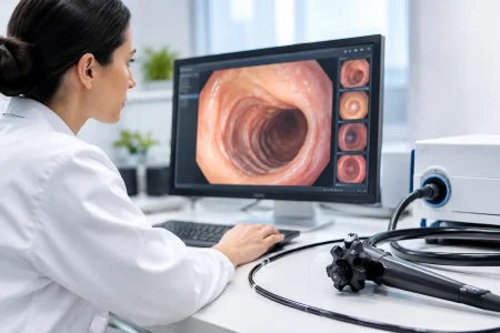
The required test depth depends on the application. A consumer accessory may prioritize rapid assembly and low cost. A factory vision node may need extended vibration and temperature testing. Medical and endoscope imaging equipment can require tighter control of cable routing, cleaning exposure, connector accessibility, and traceability. There is no universal connector architecture that is best for every camera module.
Plan connector integration for manufacturing
Many integration problems originate when a prototype-oriented design reaches production. A connector that was easy for an engineer to mate with tweezers may be slow, inconsistent, or damage-prone on an assembly line. Production planning should define insertion force, locking verification, inspection points, cable orientation, ESD controls, and rework procedures before the pilot build.
Supplier consistency also matters. Connector substitutions should never be made solely on nominal dimensions. Contact plating, retention force, coplanarity, material behavior, and quality control can vary between sources. For long-life OEM programs, qualify the connector, flex cable, camera module, and host-board assembly as a controlled combination.
SincereFirst supports this process by aligning camera module configuration, interface definition, flex routing, and connector requirements during custom development. For OEM and ODM teams, this reduces the risk of receiving a camera module that meets a datasheet target but creates avoidable integration work at the device level.
The most efficient next step is to review the actual module pinout, host processor, enclosure layout, and operating environment together before committing to the PCB. A connector decision made early with complete system information protects schedule, image quality, and production yield when the product moves from sample to scale.