A camera module can look correct on a drawing and still fail inside the finished device. The lens may sit too high for the enclosure, the MIPI timing may not match the processor, or low-light noise may make the intended image-processing algorithm unreliable. A disciplined camera module sampling process exposes these risks while changes are still fast, affordable, and technically manageable.
For OEM teams developing robotics equipment, medical devices, industrial tools, security hardware, or smart terminals, sampling is not simply a stage for receiving a few parts. It is the engineering bridge between an imaging requirement and a production-ready module. The objective is to confirm optical performance, electrical compatibility, mechanical fit, and manufacturing feasibility before committing to volume production.
Start With a Requirement That Can Be Tested
The strongest sample programs begin with measurable requirements, not a general request for a “high-resolution camera.” Resolution matters, but it is only one part of the imaging system. A 5MP module may outperform a higher-resolution option when lens selection, field of view, illumination, frame rate, and processing requirements are correctly matched to the application.
Before sample design begins, the camera supplier and customer should align on the essential operating conditions. These usually include:
- Target sensor, resolution, frame rate, and output format
- Interface requirements such as MIPI CSI-2, USB, DVP, or UVC
- Field of view, working distance, focus method, and distortion limits
- Module dimensions, FPC length, connector position, and mounting constraints
- Operating temperature, illumination environment, and reliability expectations
Application context changes the correct solution. A warehouse robot may need a wide field of view and low motion blur. A handheld medical device may prioritize compact dimensions, consistent color response, and controlled illumination. An endoscope module may require an extremely small diameter, precise LED integration, and stable performance through a narrow optical path.
When these details are defined early, the supplier can recommend a standard module, a modified design, or a fully customized solution with a clear technical basis. This avoids a common failure mode: selecting a module for its sensor specification, then discovering that its lens, interface, or physical structure cannot support the actual product.
Camera Module Sampling Process: From Review to Build
A practical sampling process normally moves through requirement review, architecture selection, engineering confirmation, prototype build, and validation. The sequence may compress for a catalog USB camera module, while a custom MIPI or miniature endoscope design may require multiple iterations.
1. Evaluate the imaging architecture
The first engineering review assesses the complete signal chain. Sensor selection is considered together with the lens, image signal processor, interface, host platform, cable or FPC design, and application software. This systems view matters because image quality is influenced by every connection in the path.
For example, a MIPI module can provide low latency and a compact integration route, but it requires host-side compatibility with lane count, clock rate, data format, and driver support. A USB UVC camera module can shorten software integration because it follows a widely supported standard, but it may not fit a space-constrained embedded design. There is no universally best interface. The right choice depends on the device architecture, production target, and required development speed.
Lens selection is equally consequential. Engineers review focal length, F-number, image circle, chief ray angle, distortion, depth of field, and focus tolerance. If the module will inspect objects at a fixed distance, fixed focus may provide the best stability and cost control. If the application must capture targets at varying distances, autofocus or a carefully optimized depth of field may be necessary.
2. Confirm mechanical and electrical details
Once the architecture is selected, the team converts requirements into drawings and build specifications. This step should define the module outline, component keep-out areas, connector orientation, FPC bend requirements, mounting holes, heat-sensitive zones, and optical axis position.
Small dimensional decisions can determine whether a camera integrates cleanly. A connector placed a few millimeters in the wrong direction can complicate assembly. An FPC that bends too sharply may create long-term reliability concerns. A lens barrel that clears the mechanical envelope but has insufficient adjustment range can delay focus calibration.
Electrical confirmation covers pin definitions, voltage requirements, power sequencing, clocking, reset behavior, I2C control, and output configuration. For custom camera modules, the sample phase is also the right time to clarify whether the module will ship with default register settings or require a customer-specific tuning profile.
3. Build engineering samples under controlled conditions
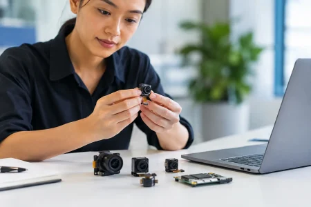
Engineering samples should be produced with the same discipline expected for future production. At SincereFirst, this means connecting optical assembly, cleanroom manufacturing controls, sensor handling, FPC assembly, and functional testing into one coordinated process.
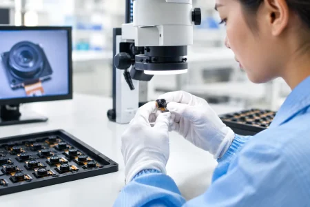
The build typically includes component preparation, SMT or FPC assembly, sensor placement, lens installation, focus adjustment, curing where required, and initial electrical verification. For modules using fixed-focus lenses, focus is set against the defined target distance and image-quality criteria. For autofocus or specialized optical assemblies, the process may also include actuator checks and control verification.
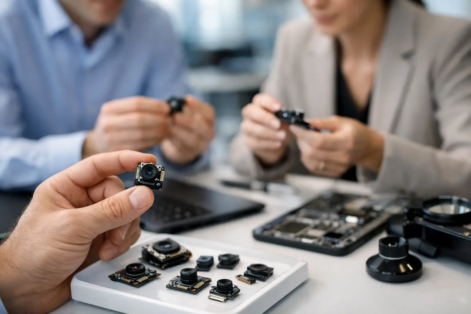
Sample quantity depends on the program. A first evaluation may require only a small number of units for host-board bring-up and mechanical fitting. A later pilot build may require a larger lot to evaluate assembly variation, tune manufacturing parameters, and support reliability testing. Treating these as separate stages prevents teams from making volume decisions based on one hand-built prototype.
Validate More Than Image Resolution
A successful camera sample must prove performance in the intended product environment. A test chart in a controlled lab is useful, but it does not replace real application validation. The evaluation plan should reflect the conditions the device will encounter in service.
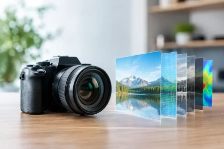
Optical validation commonly reviews sharpness across the field, focus consistency, field of view, distortion, color reproduction, signal-to-noise ratio, dynamic range, low-light behavior, and unwanted artifacts such as flare or shading. Requirements should be tied to acceptance criteria. “Clear image” is subjective; a specified center and corner resolution threshold at a defined working distance is testable.
Electrical and system testing confirm that the module starts reliably, communicates correctly with the host, maintains stable frame output, and operates under expected bandwidth conditions. Teams should also test exposure control, white balance, frame synchronization when multiple cameras are used, and compatibility with the target operating system or processor pipeline.
Mechanical validation checks fit inside the final housing, connector accessibility, FPC routing, vibration sensitivity, and tolerance stack-up. This step is particularly important for compact modules where lens height, sensor location, and enclosure features have little margin. A module that works on an open development board may behave differently after being installed behind a cover glass, inside a metal enclosure, or near heat-generating components.
Environmental testing should be scaled to product risk. Industrial, automotive-adjacent, medical, and outdoor equipment may need temperature cycling, high-temperature operation, humidity exposure, vibration, drop, or cable flex testing. Not every camera module requires every test, but omitting the tests that match the application can create costly field failures later.
Use Sample Feedback to Control Design Changes
Sampling creates value when findings are documented and converted into controlled decisions. After the first prototypes are evaluated, the customer and supplier should review deviations, root causes, and corrective actions. A poor edge image may require lens adjustment or a different optical design. Frame instability may point to host configuration, power integrity, or interface timing rather than the module itself.
This is also the point to separate must-fix issues from preference changes. A mechanical interference or unstable video stream must be corrected before pilot production. A preference for a slightly wider field of view may be valid, but it can affect lens cost, distortion, module height, and development timing. Clear change control helps keep the program moving without losing sight of the commercial target.
For custom projects, a revised sample is often the right next step. The fastest path is not always the one with the fewest sample rounds. One additional, well-defined iteration can prevent a much larger redesign after tooling, certification, or production launch.
Move From Approved Samples to Repeatable Production
Sample approval should lead to a production package, not an informal assumption that the evaluated parts will be reproduced exactly. The package should lock the bill of materials, drawings, optical specifications, firmware or register settings, test method, cosmetic criteria, packaging requirements, and revision controls.
Manufacturing test limits should reflect what was proven during sampling. If focus, active alignment, image output, or cosmetic inspection are critical to the application, they need defined controls in production. Traceability for key components such as sensors and lenses may also be necessary, especially for regulated or high-reliability applications.
The camera module sampling process is complete only when the approved design can be built repeatedly at the required quality level and volume. A sample proves possibility. Production validation proves confidence. For OEM teams, that distinction is where a promising camera design becomes a dependable imaging component in the products customers rely on.