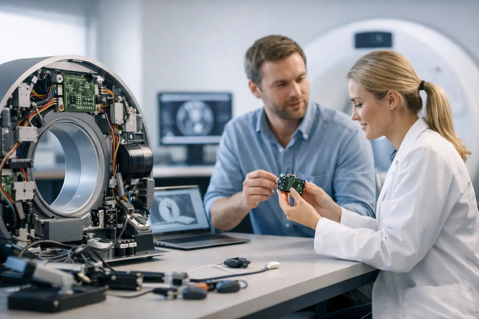
A medical imaging prototype can produce a beautiful image on a lab bench and still fail as a product. The usual causes are not only sensor resolution. Heat, illumination uniformity, lens tolerances, cable routing, electrical noise, cleaning requirements, and repeatable assembly can all change image quality. Learning how to prototype medical imaging hardware means engineering the entire imaging path for the clinical task, then proving that it can be built consistently.
For OEMs, product teams, and system integrators, the objective is not simply to assemble a camera. It is to reduce technical and manufacturing risk early enough that the final design can meet performance, regulatory, usability, and supply-chain requirements without repeated redesign.
Start With the Imaging Task, Not the Camera Module
Define what the system must reveal and under what conditions. A wound imaging device may prioritize true color, controlled illumination, and repeatable working distance. A dental camera may require close-focus performance, low motion blur, and a compact housing. An endoscopic platform has much tighter constraints around outer diameter, flexible cable routing, waterproofing, thermal control, and illumination at the distal tip.
Write an image-quality requirement that can be measured. Instead of specifying “high-definition image,” define the smallest feature that must be visible, the field of view, the target working-distance range, acceptable distortion, minimum frame rate, color performance, and maximum acceptable latency. Include the environment: ambient light, specular tissue, condensation, fluid exposure, movement, and whether the device is used once, repeatedly, or under a sterile barrier.
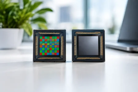
This step determines whether a standard camera module is appropriate or whether the application needs a custom optical stack. It also prevents a common procurement mistake: selecting a sensor by megapixel count before confirming pixel size, sensitivity, rolling versus global shutter behavior, and lens compatibility.
Choose the Sensor, Optics, and Interface as One System
A medical imaging module is an interdependent system. Sensor format affects lens choice. Lens focal length and aperture affect illumination demand. The output interface affects cable length, processor selection, power design, and mechanical packaging.
For early prototypes, use a sensor with enough resolution to exceed the minimum diagnostic or visualization requirement, but avoid overspecifying it. More pixels may increase bandwidth, processing load, heat, storage needs, and cost without improving usable clinical information. Small-pixel sensors can make compact designs possible, yet their low-light performance may require stronger illumination or more aggressive image processing.
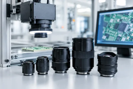
Optics deserve equal attention. Evaluate field of view, depth of field, chief ray angle, distortion, relative illumination, flare, chromatic aberration, and focus stability over temperature. In close-range imaging, depth of field is often the constraint that determines whether a fixed-focus lens will work. In a device with a known object distance, fixed focus can reduce size, cost, and failure modes. Where working distance changes significantly, autofocus or a carefully selected extended-depth-of-field approach may be justified, but each introduces validation and integration work.
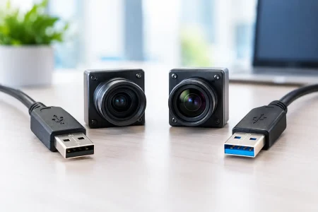
Select the interface based on the prototype architecture and final product direction. MIPI CSI-2 is well suited to compact embedded systems with a short board-level connection and a capable application processor. USB UVC can speed desktop evaluation and simplify host compatibility. USB 3.0 supports greater data throughput for higher-resolution or higher-frame-rate video, while DVP may remain relevant for legacy processors and lower-complexity embedded platforms. Do not treat the evaluation interface as a temporary convenience if it forces a complete electronics redesign later.
Build the Prototype in Stages
The fastest path is usually a sequence of controlled prototypes, not one attempt at a finished enclosure. Separate the questions that must be answered in each build.
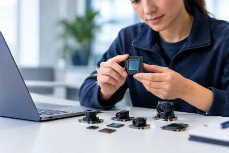
The first stage should establish image feasibility. Use an available module, evaluation board, known lens, controlled target, and basic illumination to confirm field of view, resolution, exposure behavior, motion artifacts, and color rendering. This is the point to compare sensor candidates and optical configurations quickly.
The second stage should become a form-factor prototype. Introduce the intended cable, mechanical envelope, thermal path, light source placement, front window, and housing materials. Imaging often changes substantially here. A protective window can create reflections and reduce contrast. A tight housing can trap heat. An LED ring that looks acceptable on a flat test chart may produce glare on curved, wet, or reflective anatomy.
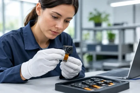
The third stage should be a design-verification prototype that resembles production intent. Use production-representative printed circuit boards, connectors, flex cables, mounting methods, firmware, and assembly processes. This version is where repeatability matters. A single hand-tuned sample is not evidence that the system can be manufactured.
Engineer Illumination and Thermal Behavior Early
Many medical camera programs underestimate lighting. The sensor captures only the light delivered to the target, and illumination design controls color fidelity, shadowing, glare, exposure stability, and heat.
Specify LED wavelength distribution, color temperature, color rendering goals, optical output, drive current, duty cycle, and placement relative to the lens. Diffusers, light guides, polarizers, and angled emitters can improve usable images, but each consumes space and reduces available light. Cross-polarization can suppress surface glare in some applications, for example, but it also reduces signal and may require a more sensitive sensor or higher light output.
Thermal design must cover both user safety and imaging stability. Sensor dark noise, LED output, lens focus position, and color balance can shift with temperature. Measure the device after realistic continuous operation, not only immediately after power-on. If the camera is distal, miniature, or enclosed, identify the heat path before finalizing the mechanical design. Reducing LED duty cycle, improving heat conduction, or moving power electronics away from the imaging head may be more effective than trying to correct thermal image changes in software.
Design Electronics for Image Integrity
Medical imaging hardware frequently combines sensitive analog imaging, high-speed digital data, LEDs, displays, radios, and charging circuits in a compact enclosure. That is a noise problem before it becomes a software problem.
Use disciplined power sequencing, low-noise sensor rails, appropriate decoupling, controlled-impedance high-speed routing, and a ground strategy that matches the module and processor requirements. Keep switching regulators and high-current LED paths away from sensitive sensor and clock routes where practical. Validate for fixed-pattern noise, horizontal banding, dropped frames, MIPI errors, USB disconnects, and image instability across battery voltage and operating temperature.
Firmware should expose the controls needed for disciplined testing: exposure, gain, white balance, frame rate, focus if applicable, LED current, and image-processing settings. Automatic functions can make a prototype look impressive in an informal demo while masking weaknesses. For engineering comparison, capture raw or minimally processed images when possible and log the operating conditions for every test.
Plan for Medical Device Controls Before Verification
A prototype is not a cleared medical device, but it should be built with the final development pathway in mind. Risk management should begin while architectural choices are still flexible. ISO 14971-style hazard analysis helps teams identify risks such as misleading image quality, excessive optical output, excessive surface temperature, electrical faults, contamination pathways, dropped frames, or loss of image data.
The applicable standards and regulatory pathway depend on device classification, intended use, market, patient contact, and whether the image supports diagnosis, treatment, navigation, or simple visualization. Electrical safety and essential performance considerations may involve IEC 60601 requirements. If the product includes software used in a medical device context, software lifecycle planning and cybersecurity controls should also be considered early. A qualified regulatory strategy is necessary before making compliance claims or beginning formal verification.
Translate risks into testable engineering requirements. For example, if clinicians must distinguish fine vessel detail at a set distance, test contrast and resolution on representative targets at that distance, across multiple samples and operating temperatures. If color differentiation affects intended use, establish a controlled color target, illumination condition, and acceptance range. Requirements without a test method become expensive arguments later.
Prototype for Manufacturing, Not Just Demonstration
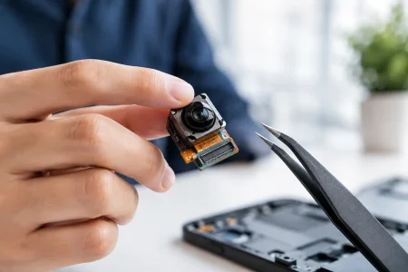
The final prototype phase should expose supplier and assembly risks. Define tolerances for sensor-to-lens alignment, lens focus position, LED placement, flex bending radius, adhesive dispensing, connector retention, and front-window alignment. An optical design that needs individual manual focus adjustment may be acceptable for a very low-volume specialty device, but it is a weak foundation for scaled production unless the adjustment process is controlled and validated.
Ask manufacturing partners how they will inspect the module. A practical production plan may include incoming inspection, active alignment or focus checks where needed, image quality testing, cosmetic inspection, electrical functional test, and traceability by lot or serial number. The right test depth depends on risk and volume, but the principle is constant: the inspection process must detect the defects that matter to clinical use.
SincereFirst supports this transition by combining standard and customized camera module development with optical integration and production-oriented manufacturing capability. For compact medical imaging and endoscope designs, early discussion of sensor availability, interface, cable construction, lens selection, and assembly tolerances can shorten the path from feasibility sample to stable supply.
How to Prototype Medical Imaging Hardware With Clear Decision Gates
Set decision gates around evidence, not calendar dates. At image feasibility, decide whether the selected sensor and optics meet the defined imaging task. At form-factor validation, decide whether illumination, thermal behavior, cable routing, and housing constraints preserve that performance. At production-intent validation, decide whether repeated units meet the same criteria with a documented assembly and test process.
Keep a small set of reference scenes and targets throughout development. Re-test them whenever the sensor, lens, window, LED, firmware, enclosure, or cable changes. Those controlled comparisons reveal regressions that are easy to miss when teams rely on subjective live viewing.
A strong prototype earns confidence because it answers the next commercial question: not merely “can this image be captured?” but “can this image be captured reliably in the intended device, by repeatable hardware, at the volume the program requires?”